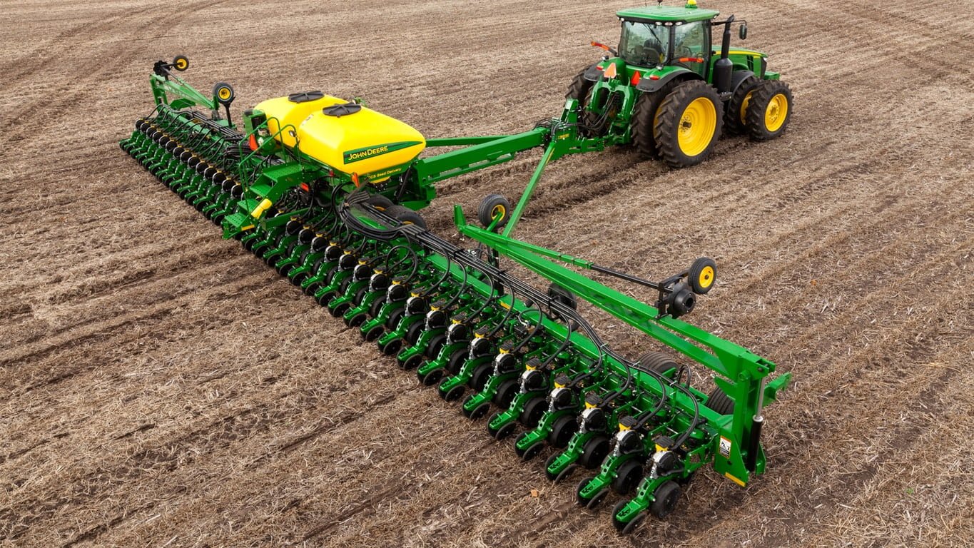
- 60 ft. (18.29 m) toolbar with 24 rows on 30 in. (762 mm) spacing
- Available in mini-hopper, 1.6 bu., or 3 bu. MaxEmerge™ 5 row unit
- Insecticide option for mini-hopper
- Requires a minimum 175 kW (235 hp) tractor equipped with Category 4 drawbar
Features
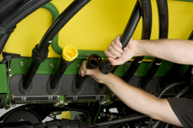
Easy fluid transfer with the ExactRate™ fluid transfer system
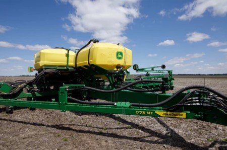
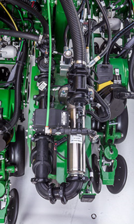
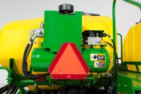
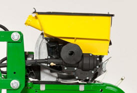
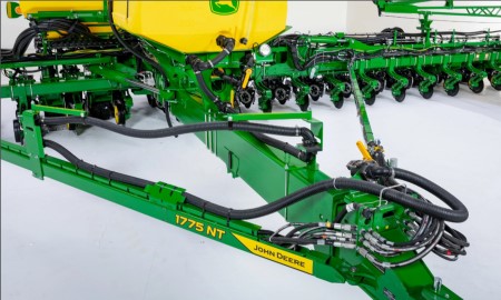 24-row 1775NT Planter equipped with ExactRate system
The ExactRate fluid transfer system pairs planters seamlessly with the ExactRate tractor tanks. It provides an easy connection point to allow transfer from the ExactRate tractor tanks back to the planter tank. This enables up 6056 L (1600 gal.)* of combined capacity between the tractor and planter tanks.
- Factory installed
- Designed and tested by John Deere to ensure the lines won’t pinch when folding
- Easily attaches to the ExactRate tractor tanks
ExactRate is available on the following models: 1775NT, 1795, DB44, DB60, and DB66.
*NOTE: 6056 L (1600 gal.) assumes a 2271-L (600-gal.) tank on a 24-Row 1775NT Planter as well as the 3785-L (1000-gal.) capacity on the 8RX Tractor.
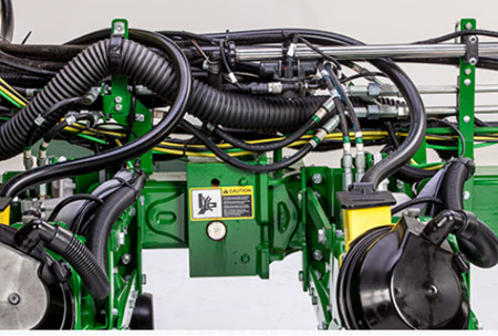
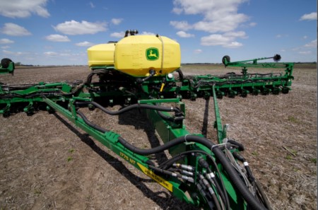 24-row 1775NT Planter equipped with ExactRate fluid transfer system
Easily carry fluid on the planter with liquid tanks
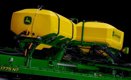 Liquid tank mounted on a 24-row 1775NT Planter
John Deere factory-installed liquid tanks offer a convenient way to carry fluid on the planter frame. Styling cues match the CCS™ system tanks, and all brackets and mountings are 100 percent factory installed.
- Factory installed
- Up to 2271 L (600 gal.) of fluid capacity
- Clear sight tube to check fluid level
- Air bleed and overflow protection
 Liquid Tank mounted to a 24-row 1775NT Planter
SeedStar™ 4HP monitoring system – see speed meet accuracy in real time
Have you wanted to view more than one planter chart at once? SeedStar 4HP gives you multiple views and configurations in one simple overview page to fit your preferences. You can complete the simplified setup from the Work Setup page instead of having multiple applications to open.
SeedStar 4HP is designed to optimize the in-cab monitoring experience exclusively on the Gen 4 4600 CommandCenter™ display or 4640 Universal Display for growers with ExactEmerge™ planters and MaxEmerge™ 5e planters. With SeedStar 4HP, operators will easily see key planter information with customizable run pages, zoom functionality, and simultaneous graph and performance measurements. SeedStar 4HP is included in base on all model year 2018 ExactEmerge and MaxEmerge 5e planters.
Features overview:
- View multiple planters' at-a-glance bar charts simultaneously
- Three default planter run pages show key planter functions in easy-to-view layouts
- Highly configurable run pages allow SeedStar modules to be customizable
- Zoom feature allows quick row-by-row detailed information
- View dual bar graphs to see multiple planter details at one time
- SeedStar application to make adjustments to planter functions
- Simplified setup through the work set-up page
- Advanced rates allow up to six different rates across 48 rows
- The SeedStar 4HP monitoring system requires the Gen 4 4600 CommandCenter or 4640 Universal Display. These displays allow the operator to benefit from the updated interface, enhanced processing speeds, and easy setup (learn more in the Gen 4 CommandCenter feature).
SeedStar 3 HP conversion to SeedStar 4HP with mobile row-unit runoff aftermarket for field conversion kits
Growers who are currently running model year 2017 planters, model year 2017 and newer Precision Upgrades, or model year 2017 and newer custom-built planters with the SeedStar 3 HP monitoring system can upgrade to the SeedStar 4HP monitoring system with mobile row-unit runoff. The attachment part, AA100382, is software only. The Gen 4 display software version will need to be 19-1 or newer and will require planter apps. Follow the mobile runoff ordering and software push guide below for ordering and installation. Retrofitted planters and custom-built planters will also require the John Deere Connect Mobile kit, 0048PC, from the Precision Ag Technology Price Pages and wiring harness AA83662 to enable the mobile row-unit runoff feature. Please reference Parts Advisor and DTAC Solution 105181 for model-specific mounting brackets. SeedStar 4HP requires the Gen 4 4600 CommandCenter v2 display or 4640 Universal Display.
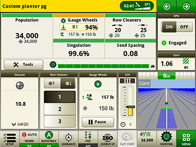
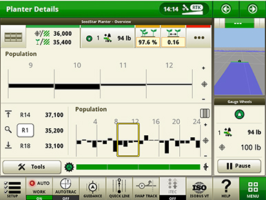
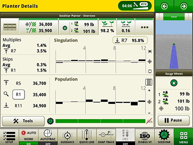
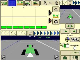
Default planter run pages
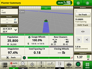 Planter summary default run page
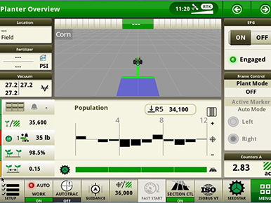 Planter overview default run page
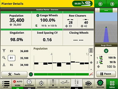 Planter details default run page
Three default run pages show key planter functions in different views to give fast and easy access to important planter information.
Custom run pages
 Customizable run pages
There are customizable run pages that allow the operator to build pages that fit their operation with different modules, like the example shown above.
Zoom functionality
 Zoom feature showing a group of rows
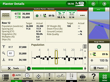 Zoom feature showing a single row
The zoom feature allows the operator to touch a section or row of the planter and get detailed information quickly.
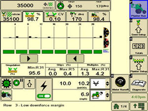
Dual bar graphs
 Dual bar graph showing singulation and population simultaneously
Dual bar graphs allow operators to view multiple planter details at one time.
SeedStar application page
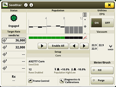 SeedStar application run page
In the SeedStar application, many adjustments can be made, including manually activating section control. SeedStar 4HP allows up to 48 individual row sections. There are several setup features such as crop, seed disk, number of rows being planted, population alarms, and limits. Seed rates can be modified, electric power generation (EPG) can be turned on or off, vacuum can be adjusted, and the fill and purge functions can be used from the SeedStar application. Frame control, as well as diagnostics and calibrations, can be accessed at the bottom of the screen.
Settings Manager in SeedStar 4HP
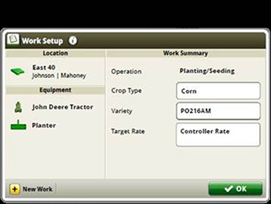
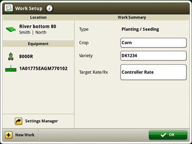 Access Settings Manager on the Work Setup screen
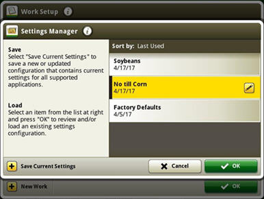 Settings Manager screen
Reduce set-up time between changing crops or field conditions by recalling saved settings used previously with Settings Manager, included with every SeedStar 4HP system. This feature allows saving and recalling planter and tractor settings for optimum performance in different conditions.
Settings Manager can be used to save all the adjustment and inputs associated to a particular crop or condition. An example would be to store all population rates, downforce pressure, row cleaner adjustments, and closing wheel settings for planting corn and storing a separate, unique set of adjustments for soybeans. In addition, Settings Manager stores tractor settings such as selective control valve (SCV) flow and detents, infinitely variable transmission (IVT™) settings, eco modes, and more.
Custom rates in SeedStar 4HP
 Variety set-up page
 Rate set-up page
 Group rate set-up page
Custom rates allow for individual row population control and row-by-row documentation where up to six different rates can be assigned across an up to 48-row planter. This allows growers interested in planting seed corn with ExactEmerge or MaxEmerge 5e the capability to assign specific populations to male and female rows for planting. This feature can also be used to create tram lines or other applications where custom rates by row are needed.
NOTE: Individual rates are tied to varieties, so each individual rate needs a unique variety name.
NOTE: Advanced rates are not compatible with prescriptions or they cannot be run at the same time.
Compatibility
| SeedStar 4HP compatibility | |
| Planters | All models ordered with ExactEmerge or MaxEmerge 5e row-units NOTE: Precision Upgrades are equipped with SeedStar 3HP only but can be upgraded by purchasing part number AA100382. |
| Displays | Gen 4 4600 CommandCenter equipped with Version 2 Processor or 4640 Universal Display Dual-display mode is compatible with mid model year 2019 planter software. |
| John Deere Active Implement Guidance™ | Compatible with SeedStar 4HP on Gen 4 displays with VT mode and required activations and subscriptions |
| AutoTrac™ Implement Guidance | SeedStar 4HP is compatible with AutoTrac Turn Automation and AutoTrac Implement Guidance; not compatible with greater than 48 row electric drive planters. |
| AutoTrac Turn Automation | SeedStar 4HP is compatible with AutoTrac Turn Automation and AutoTrac Implement Guidance; not compatible with greater than 48 row electric drive planters. |
Additional information
For additional information on feature functionality on the Gen 4 Display, visit the links below:
YouTube is a trademark of Google LLC.
Precise liquid fertilizer placement with ExactRate™ fertilizer system
 ExactRate pump assembly at rear of 12-row 1775NT
The ExactRate liquid fertilizer system is a factory-installed solution that provides you with accurate nutrient placement during planting. Previously, you would have to deal with the inconvenience of cumbersome aftermarket systems for a hydraulically driven variable-rate solution. With ExactRate, John Deere delivers a complete planting solution for liquid fertilizer users. You can choose between in-furrow or offset delivery methods. A high-rate option without openers is also offered from the factory. This system delivers:
- Up to 20 percent more accurate nutrient placement in a turn compared to a non-turn compensating system
- 1 to 12 percent (4.3 percent on average) reduction in inputs through row-by-row section control
- Ability to run up to 16.1 km/h (10 mph)
- Closed-loop speed and rate change compensation
- Full integration into the 4600 CommandCenter™ and 4640 Universal Display
 ExactRate nozzle body
The ExactRate liquid fertilizer system is designed to take full advantage of the capabilities of ExactEmerge™ and MaxEmerge™ 5e planters. This factory-installed liquid fertilizer system delivers the same value as your electric drive planter including working at speeds faster than the traditional 8.05 km/h (5 mph), turn compensation, and row-by-row section control, all while accurately compensating for varying rates and speed changes. Additional features include row-by-row flow detection, as-applied documentation, and variable-rate capabilities, providing operators full integration into the 4600 CommandCenter or 4640 Universal Display.
Fertilizer flows from the tank to the pump, through a strainer and boom isolation valve, through a central flowmeter, and out to each nozzle body and row-unit for accurate delivery. The system is closed loop, meaning the pump and nozzle body duty cycle both adjust based on feedback received from the pressure sensor and central flowmeter. This design helps maintain an accurate application rate.
NOTE: ExactRate is not recommended for products that require agitation to maintain suspension.
Pump
 Pump assembly at rear of planter
Instead of a tire-contact drive, a hydraulically driven centrifugal pump eliminates chain and sprocket adjustments to provide more speed flexibility over the entire rate range. This pump allows for a wide range of rate capabilities as well as strong durability. The wet seal design helps protect the pump if it is accidentally run dry for a short time.
Strainer
A strainer helps collect suspended particles and prevent them from causing blockages in the distribution system and nozzle bodies.
Boom isolation valve
The valve prevents the tank from draining out if there is a leak in the distribution system. If the pump is on, the valve opens to allow flow. When the pump is off, the valve closes.
Central flowmeter and pump pressure sensor
The central flowmeter and pump pressure sensor provide the rate control system feedback on flow and pressure to ensure an accurate application rate across the entire planter width. The flowmeter also supplies the as-applied rate data.
Distribution system and nozzle body
 Distribution system and nozzle bodies routed on the wing of a 12-row 1775NT
The 2.5-cm (1-in.) stainless-steel distribution lines not only reduce corrosion, but they also provide a clean integrated look. The distribution system is pressure tested at the factory to reduce the risk of leaks.
John Deere has leveraged ExactApply™ technology and capabilities from the sprayers to enable row-by-row section control and turn compensation that matches the high-performance planters. With ExactRate, there are no orifice changes for rate or speed adjustments, saving you time and effort while limiting exposure to product. Pulse-width modulation technology varies duty cycle (opening and closing of the valve) in the nozzle bodies in conjunction with flow and pressure measured from central flowmeter and pressure sensor controlling the system pump. The ExactRate liquid fertilizer system uses one nozzle body for two rows, limiting the number of parts and complexity on each machine. While you’re in the cab, you can keep an eye on each row with flow detection integrated into the Gen 4 display. The system warns you if it detects a variance in an individual row’s flow. A pressure sensor integrated into the nozzle body will detect a flow reduction or overapplication on the row.
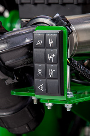 Keypad at rear of planter
Just like on the sprayers, the keypad at the rear of the machine lets you conveniently perform a nozzle flow check to ensure product is coming out of each row before going to the field.
Rate Controller
The ExactRate liquid fertilizer system is compatible with the John Deere Rate Controller 2000 and GreenStar™ Rate Controller if a producer wants to apply a second product using a separate distribution system.
Direct injection
The ExactRate liquid fertilizer system does not have direct injection capabilities on the product being applied. If direct injection is needed on the secondary product, an additional rate controller is required.
NOTE: ExactRate system and John Deere Rate Controller 2000 with Raven ICD Direct Injection system is supported. ExactRate system and GreenStar Rate Controller with Raven ISO Direct Injection system is not supported.
ExactRate app on Gen 4
Easily adjust target rate and speed without leaving your seat. With turn compensation, inner and outer rates are automatically adjusted to maintain consistent application across the full width of the planter. This ultimately reduces the risk of seed burn by over application (turn compensations require a global positioning system [GPS] receiver). Another helpful feature is row-by-row section control for reduced overlap on headlands and waterways. Gen 4 Documentation creates as-applied maps showing what product was applied where, providing accurate record-keeping.
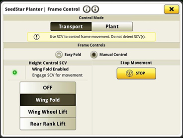
Easy Fold
Easy Fold is a feature of SeedStar™ 4HP for MaxEmerge™ 5e row-units and ExactEmerge™ row-units equipped on 1775NT and 1795 Planters with a 2-point hitch or DB Planters. This integrated solution replaces the frame-folding box like the manual fold option in SeedStar 3 HP, and it has enhanced the process by controlling and automating the selective control valves (SCVs).
The one-operation fold reduces the need for training inexperienced operators by sequencing the process correctly and reduces time spent folding and unfolding. By utilizing implement automation, the hitch will be controlled by the planter during the fold cycle. Lining up the draft tube to the wing hooks is automated through this process, reducing operator tasks. On DB models, Easy Fold simplifies the folding process functions to one SCV. A manual process is available when needed.
A manual fold option is available from the frame control page on the display for non-compatible or non-equipped tractors or planters. The manual control function is accessible from each step of the Easy Fold process, as shown below.
 Manual control option on SeedStar 4HP
 Start screen for Easy Fold
 Screen with Easy Fold enabled
 Screen with Easy Fold in process
 Easy Fold completed screen
| Easy Fold compatibility | |
| Tractors |
|
| Activation | 2-point hitch equipped planters with Easy Fold require Tractor Implement Automation activation available from the StellarSupport™ portal. This activation is tractor PIN specific and non-transferable. Included in base on model year 2018 compatible tractors. See instructions below. |
| Planters | 1775NT and 1795 with 2-point hitch and DB Planters, equipped with ExactEmerge or MaxEmerge 5e row-units |
| Display | Gen 4 4600 CommandCenter™ Display or 4640 Universal Display |
NOTE: Included in base with ExactEmerge equipped compatible planters. Optional equipment on MaxEmerge 5e equipped compatible planters.
Tractor Implement Automation activation instructions
Use these instructions to download the Tractor Implement Automation activation code at no cost.
- Go to https://www.deere.com/en/stellarsupport/
- Click Product Activation.
- Select Tractor Automation – Manage Product.
- Add or select existing tractor from list.
- Select the Activate button.
- Select Add Manufacturers drop down menu.
- Select Tractor Implement Automation – John Deere.
- Select Continue – Tractor Implement Automation – John Deere selected.
- Accept the Terms and Conditions.
- Select Finish.
- Take note of the code for use display.
- On the Gen 4 4600 CommandCenter Display or 4640 Universal Display select System, Software Manager.
- Select Activations, then Enter Code from John Deere Stellar Support.
- Enter activation code into the display in the tractor.
- Press next after activating Tractor Implement Automation.
- Take note of the activation code and press OK.
- The Tractor Implement Automation activation will appear the Software Manager screen.
NOTE: Prior to the 18.1 software release, the activation will be shown as “Unknown Implement 1” with a baler icon.
YouTube is a trademark of Google LLC.
Mobile row-unit runoff
 Row Runoff diagnostic test
 The test functions from a mobile device
 Determine optimum settings without being in the cab
The first day of planting season can be as productive as the last with mobile row-unit runoff. The mobile row-unit runoff activation on the planter main controller (PMC) allows operators to make adjustments to maximize row-unit performance from a mobile device at the rear of the planter for both preseason and in-season use - all enabled through the Equipment Mobile app.
Mobile row-unit runoff allows growers to perform test-stand functions from a mobile device connected to the planter.
The row runoff test provides complete diagnostic checks both preseason and in season. With the row-unit runoff test, the operator can make adjustments from the mobile device, including vacuum pressure, to determine the optimum meter and vacuum settings. This app functionality will help avoid making trips to the cab while validating meter performance.
During preseason planter inspections and set up, utilize the meter performance test to validate meter accuracy, similar to a test stand without leaving the farm. Test all systems on the planter, not just the meter, providing confidence that all planter systems are ready to plant. Reports are generated from the test providing information the operator can save and send for future reference.
Before heading to the field, the operator will benefit from knowing the best row-unit and vacuum settings for each variety selected to plant that spring.
See mobile row-unit runoff in action by watching the "How to Use Mobile Row-Unit Runoff" video.
Mobile row-unit runoff will work with any model year 2015 or newer ExactEmerge™ or MaxEmerge™ 5e equipped planter. Mobile row-unit runoff can be added with attachment AA93169.
For model year 2018 and newer ExactEmerge planters, mobile row-unit runoff is included in base equipment. For model year 2020 and newer MaxEmerge 5e planters, mobile row-unit runoff is included in base equipment. For planters not equipped from the factory, mobile row-unit runoff can be added with attachment AA93169. A mobile row-unit runoff and Easy Fold package can be added with attachment AA97849 (only available with 1775NT and 1795 Planters with a 2-point hitch and model year 2019 and newer DB Planters with Gen 4 based frame folding).
NOTE: Mobile runoff utilizes the Equipment Mobile app available on select iPad® tablets, iPhone® smartphones, and Android™ devices.
Mobile row-unit runoff and Easy Fold aftermarket for field conversion kits
The below software bundles include the functionality explained above for machines not ordered with the feature from the factory. Compatible machines include all the necessary sensors and harnesses needed to make the feature function. The attachment part is software only. Follow the mobile runoff ordering and software push guide below for ordering and installation.
SeedStar™ 3 HP conversion to SeedStar 4HP
Mobile runoff ordering and software push guide
iPad and iPhone are trademarks of Apple Inc. Android is a trademark of Google LLC.
Downforce system options
Individual Row Hydraulic Downforce (IRHD)
 IRHD system
IRHD has been specifically designed to meet the needs of producers that are looking to adjust to the toughest field conditions and provide maximum yield potential from field to field, season after season. IRHD works as a closed-loop downforce system that reacts quickly on an individual row basis to changing soil conditions supporting increased ground contact, which can lead to improved seed depth consistency. When setting planter downforce margin, the system will apply the needed downforce by row to maintain ground contact. From the factory, the margin will be set at 45.4 kg (100 lb), changes may be required based on varying field conditions.
The system allows operators to maintain gauge wheel ground contact leading to desired seed depth placement. IRHD can adjust five times per second and make adjustments of 45.4 kg (100 lb) in less than a second. The system has a total range of applied downforce from 22.7 kg (50 lb) to 204.1 kg (450 lb) and utilizes the power beyond circuit on the tractor. IRHD is 58 percent faster than the active pneumatic downforce solution. Fast reaction and increased ground contact can lead to improved emergence. With uniform emergence, some studies have shown a yield impact from 5 percent to 9 percent.
IRHD is controlled through the display with SeedStar™ 3 HP or SeedStar 4HP. As shown below, operators can view ground contact or applied downforce using the toggle button.
 IRHD screen showing the ground contact graph through SeedStar 4HP
 IRHD screen showing the applied downforce graph with SeedStar 4HP
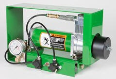
Hydraulically driven compressor
 Pneumatic valve
The hydraulically driven air compressor can deliver up to eight times the air flow when compared to the electric compressor, allowing for more and faster downforce changes to be made. This more robust design features a 37.8-L (10-gal.) storage tank across all models with active downforce.
At approximately 15.1 L/min (4 gpm), hydraulic demands are low and ties into the machine’s lift and Central Commodity System (CCS™) hydraulic circuit so it does not require any additional selective control valves (SCVs). The SeedStar XP, SeedStar 3 HP, and SeedStar 4 HP monitoring systems work with the compressor. SeedStar 3 HP and SeedStar 4 HP monitoring systems work with the compressor and valve assembly to regulate air to downforce springs, enabling the active control, pneumatic closing wheels, and pneumatic row cleaners.
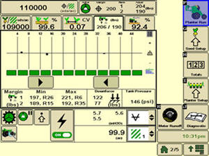
Row-unit downforce planter run page
 SeedStar XP downforce planter run page
Active downforce control is integrated into SeedStar XP, SeedStar 3 HP, and SeedStar 4 HP monitoring systems.
Margin is the amount of weight riding on the depth gauge wheels that ensures desired firming of the seedbed as set by the operator.
Once a target margin has been defined, enter the value into the display and let active downforce do the rest. The system will actively adjust the air pressure in the air bags to maintain a constant margin across the planter. The changes in air pressure will change the amount of downforce placed on the row-unit, compensating and reacting for varying conditions through the field whether it is different tillage practices, soil types, or moisture.
 Downforce and margin example
- A - Margin – amount of additional downforce applied to a row-unit above and beyond what is required for penetration to achieve planting depth. This additional weight will ride on the depth gauge wheels.
- 54.4 kg (120 lb) + 36.3 kg (80 lb) = 90.7 kg (200 lb) – 68 kg (150 lb) = 22.7 kg (50 lb) of margin
- B - Weight of row-unit - 54.4 kg (120 lb)
- C - Downforce – force that is applied to the row-unit by the air bag circuit - 36.3 kg (80 lb)
- D - Resistance from soil - 68 kg (150 lb)
Margin video references:
Using Active Pneumatic downforce
 Active downforce compressor assembly
A hydraulically driven compressor works with the SeedStar XP, SeedStar 3 HP, and SeedStar 4 systems to automate downforce control. Just set the row-unit target margin value and the active pneumatic downforce system works automatically. The system will make sure the planter maintains this value, achieving precise soil penetration, and consistent planting depth, without sidewall soil compaction. From the factory, the system is set at 45.4 kg (100 lb) target downforce margin but may be modified for varying field conditions. This frees the operator from constantly making manual downforce adjustments as conditions change.
Active pneumatic downforce is available as factory installed or as an attachment for field conversion.
Set point row-unit downforce
 Pneumatic downforce control in GreenStar 2 Display
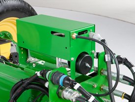 Air compressor mounted on 1775NT outer hitch
On set point, the air compressor will be mounted on the outer hitch or frame assembly. Since the electric air compressor assembly is mounted on the outer hitch (as noted in the picture above) or frame, adjustments for row-unit downforce and related system pressures will be made electronically with the GreenStar display.
When adjusting the amount of row-unit downforce using the GreenStar display, the operator will select the amount of downforce (kg [lb]) to be applied across the planter. Depending on the soil conditions at hand, the operator might need to adjust the relative amount of row-unit downforce being applied during the planting operation. The integrated pneumatic downforce controls within the GreenStar display will only allow for set-point operation and not automatic control as the planter is operating in different soil conditions. The pneumatic downforce system does not have the capability to automatically adjust downforce.
Pneumatic downforce provides convenient, simple adjustment of downforce for the whole planter from one location. The amount of downforce applied is infinitely adjustable from 6.8 to 181.4 kg (15 to 400 lb). Pneumatic downforce provides more consistent downforce throughout the range of row-unit travel than mechanical spring downforce systems.
Features include:
- 9.5-mm (3/8-in.) air delivery line instead of the 6.4-mm (1/4-in.) line used on model year 2010 and older planters.
- Air compressor assembly increased duty cycle. With this compressor, it provides a 47 percent increase in maximum air flow delivery compared to the prior air compressor.
- Pneumatic air bags with 9.5-mm (3/8-in.) air line inlets that have greater durability.
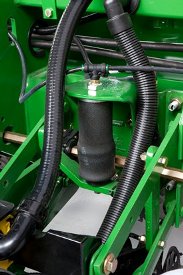 Pneumatic downforce spring
Each row-unit has a single rubber air bag located between the parallel arms. The air bags are hooked in parallel so that air can be added or released from all rows at once from one location.
The individual pneumatic downforce air bag assemblies, air compressor units, and 9.5-mm (3/8-in.) delivery lines are also available as an attachment for field conversion.
 Pneumatic downforce compressor and gauge
An improved compressor is used to charge the pneumatic system. This compressor can be located on the planter frame or in the tractor cab if desired. A gauge at the compressor indicates the amount of downforce being applied.
Integrated pneumatic downforce system
The functional features of the integrated system are the same as the standard pneumatic system, explained above, with the addition of control through the GreenStar display.
Heavy-duty adjustable downforce springs
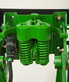 Heavy-duty adjustable downforce spring
Planter row-unit downforce is an important factor to ensure consistent and proper depth control. The heavy-duty adjustable downforce feature provides up to 181.4 kg (400 lb) of downforce. There are four settings available to allow the operator to choose the amount of downforce required for the condition: 0 kg (0 lb), 56.7 kg (125 lb), 113.4 kg (250 lb), and 181.4 kg (400 lb).
Easy Adjust row cleaners
 Coulter combo row cleaner
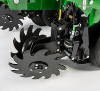 Easy Adjust row cleaner
Easy Adjust row cleaner and coulter combo provides a pneumatic row tillage solution that is controlled from the seat of the tractor.
Every decision to make an adjustment during spring planting reduces the acres planted per day and can increase or decrease profitability. An adjustment that can be overlooked is row cleaners due to planter size, difficulty to make the adjustment, and varying conditions across fields and time.
 GreenStar™ 3 2630 Display view for row cleaners compatible with SeedStar™ 3 HP
 4600 CommandCenter™ Display and 4640 Universal Display view for row cleaners compatible with SeedStar 4HP
With the Easy Adjust row cleaners on ExactEmerge™ planters, operators now have a pneumatic solution to make on-the-go adjustments that is controlled directly from the seat of the cab. They can be raised from the cab as needed with the push of a button for wet areas, waterways, or end rows. For growers using SeedStar 3 HP, the row cleaners are completely integrated into the John Deere GreenStar 3 2630 Display as well as the Gen 4 4600 CommandCenter display or 4640 Universal Display. For growers using SeedStar 4HP, a 4600 CommandCenter display or 4640 Universal Display is required.
The Easy Adjust row cleaners have the capability to save three presets for varying ground engagement based on field conditions. The system is controlled in three sections: at each wing as well as the center (frame or wheel) track rows. The pneumatic lines use air from the active pneumatic downforce compressor, requiring no additional compressor to be installed on the planter. The Easy Adjust row cleaners utilize down and up force air bags. The adjustable air pressure setting for each bag allows the operator to set the ride of the row cleaner depending on the field conditions and the desired results. Making these on-the-go adjustments from tractor cab increases productivity and performance during planting.
For Easy Adjust row cleaner Precision Upgrade options, see the ordering guide.
The row cleaner-only option utilizes parallel linkage to provide the floating action growers require in their fields. Parallel linkage allows for the unit to float up and down in the situation of hills or hard objects. The cleaner and coulter combo does not have parallel linkage, however, the row cleaners have floating rings installed to help provide the same benefits.
The row cleaners utilize the field-proven SharkTooth® design. Row cleaners play a major role in maximizing yield toward uniform emergence, reducing row-unit bounce, and maintaining proper depth. The Easy Adjust row cleaners provide growers with quick and stress-free solutions to customizing the planter in variable field conditions. They are available on most ExactEmerge and MaxEmerge 5e equipped planters.
SharkTooth is a trademark of Yetter Manufacturing Incorporated.
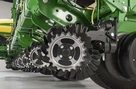
Pneumatic closing wheels
Pneumatic closing wheels are compatible with MaxEmerge™ 5e and ExactEmerge™ row-units. They are available on the following models from the factory: 1775NT, 1795, and DB60 models. The pneumatic closing wheels give operators the ability to adjust closing wheels in seconds without leaving the cab of the tractor.
Using the GreenStar™ 3 2630 Display, pneumatic closing wheels can be adjusted to 25 different positions. From the factory the system is setup with two sections, the outer wings and center frame. With this system, producers will see up to a 76 percent increase in consistent force applied at the closing wheel. Consistently applying the correct force at the seed trench is one of the key elements of supporting improved emergence. Studies show potential yield impact on corn from even emergence from 5 percent to 9 percent*.
NOTE: Pneumatic closing wheels can be purchased for existing MaxEmerge 5e and ExactEmerge planters as an aftermarket field kit. Both rubber tire and cast-iron closing wheels are compatible.
Access the pneumatic closing wheels attachment for field conversion (AFC) ordering guide to fit a 1725 CCS, 1775NT, 1795, or DB60 Planter.
*Planting Outcome Effects on Corn Yield: Doerge, Tom, Jeschke, Mark and Carter, Paul
Achieve accuracy with curve compensation
 Curve compensation with planters
Terraces or waterways are two of many field obstacles that make planting on a curve challenging. When planters utilize drive shafts, they are not able to control each individual row-unit; as a result, planting on a curve presents an issue of maintaining 100 percent population. Since the inside rows are moving slower than the outside rows, the inside rows will be overpopulated while the outside rows are underpopulated.
With ExactEmerge™ planters and equipped MaxEmerge™ 5e planters, the curve compensation feature allows each row to receive an individual signal based on the speed at which the row-unit is moving, maintaining the correct population across the width of the planter. Without curve compensation, there could be as much as a 24 percent drop in population accuracy, which is equivalent to 8,600 seeds per acre when planting at 36,000 seeds per acre. Curve compensation measures acceleration within the main planter controller and utilizes speed inputs to ensure each row has the desired population accuracy.
Row cleaner options to meet residue management needs
Crop yields have increased through the years along with the amount of residue left in the field after harvest. At the same time, tillage practices have changed, including different tillage operations which maintain large amounts of surface residue, and even no-till practices. Row cleaners are an essential tool in managing this increased amount of residue.
John Deere seeding group offers a variety of row cleaner options to meet the needs of a producer's operation. Compatibility varies by model, row spacing, and other planter equipment.
Screw-adjust, unit-mounted row cleaner
 Screw-adjust, unit-mounted row cleaner
The screw-adjust, unit-mounted row cleaner is mounted directly to the face plate of the row-unit, placing the ground engaging components just in front of the row-unit opener blades and depth gauge wheels. This close proximity allows the gauge wheels to control the depth of the row cleaner as well as the row-unit. This compact design also allows greater compatibility with fertilizer openers and other planter attachments.
SharkTooth® wheels are standard equipment on the unit-mounted row cleaner. The swept-tooth design of the wheel provides a clear path for the row-unit openers while resisting residue buildup on the wheel. The screw adjustment knob is accessible through the top of the parallel arms, providing convenient access for adjustments. The row cleaner can be adjusted in 1.6-mm (1/16-in.) increments, providing plenty of flexibility to meet the needs of changing conditions.
Floating row cleaner with unit-mounted coulter
 Floating row cleaner with unit-mounted coulter
The floating row cleaner allows a row cleaner to be used in conjunction with a unit-mounted coulter. This combination is often desired in heavy residue loads and reduced tillage planting conditions. The row cleaner provides a clear path for the row-unit, while the unit-mounted coulter helps penetrate tough soil conditions.
Accommodating the unit-mounted coulter means the residue wheels are farther forward from the row-unit face plate than in the case of the screw-adjust row cleaner. To maintain performance, this row cleaner has the capability to float above a defined minimum depth.
Standard depth-gauging bands on the wheels allow the row cleaner wheels to float independently of the row-unit openers, allowing both to perform in varying terrain. The unit may also be set in a fixed position by simply pinning through the bracket if desired. This row cleaner also features SharkTooth wheels as standard equipment.
The floating row cleaner and unit-mounted coulters are available on many planters as factory-installed equipment.
NOTE: Screw-adjust row cleaners are not compatible with MaxEmerge™ 5e row-units with long parallel arms.
NOTE: DB models have the option for either unit-mounted coulter, screw-adjust row cleaners, or pneumatic row cleaners (only compatible with MaxEmerge 5e or equipped ExactEmerge™ models). The DB60T is only available with a less row cleaner option.
SharkTooth is a trademark of Yetter Manufacturing, Inc.
RowCommand™ individual-row control system
RowCommand controls seed output
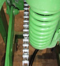
 RowCommand on a MaxEmerge™ 5 row-unit
 RowCommand on a chain drive MaxEmerge 5 row-unit
Controlling input costs and improving productivity are key producer requirements today. RowCommand is an effective, integrated John Deere solution designed to meet these intensifying needs. The RowCommand system manages seed output, reduces yield drag, and improves harvest capabilities on all Pro-Shaft™ driven row-units, and chain-driven MaxEmerge 5.
NOTE: Chain-drive RowCommand is only compatible with planters equipped with pneumatic downforce systems. On planters equipped with the heavy-duty downforce springs, potential chain interference may result and is not recommended.
NOTE: Chain-drive RowCommand requires some modification to brackets in order to function with corn finger pickup meters.
NOTE: Pro-Shaft drive RowCommand is compatible on MaxEmerge 5 row-units with vacuum and corn finger pickup meters. For mini-hopper row-units, RowCommand is compatible on vacuum meters only and is not compatible on corn finger pickup meters. Pro-Series™ XP row-units with corn finger pickup meters are not compatible with RowCommand.
RowCommand controls seed output by incorporating individual, low amperage clutches inside the Pro-Shaft and chain-driven gearboxes. Clutches are completely enclosed within the gearbox housing to protect them from the elements and harsh operating conditions.
When power is supplied, either manually or through John Deere Section Control software, clutches disengage the seed meters and seed flow stops. Controlling seed output at individual rows reduces overplanting in point rows and maximizes seed placement when entering/exiting headlands.
Components and operation
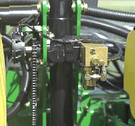
 Electronic power modules shown on a 1775NT Planter
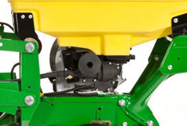 RowCommand clutch on MaxEmerge 5 with 105.7-L (3-bu) hopper
RowCommand is a simple and efficient solution to control individual row planting. This system does not utilize air to operate; therefore, no compressor, air lines, or valve modules are required.
RowCommand utilizes low-voltage controller area network (CAN) messaging to signal power to the desired clutches to stop planting or eliminates power to resume planting.
This means very little power is used in normal planting conditions, and in the event a clutch fails electrically, the meter will continue to plant.
The RowCommand system requires the following five basic components to operate:
- Electric clutches
- Electronic power modules (EPMs)
- SeedStar™ 2 or XP monitoring (wedge box/controller)
- GreenStar™ display
- Planter wiring harnesses
Clutches are protected within the sealed Pro-Shaft and chain-driven gearboxes for years of trouble-free operation and simple installation or removal. RowCommand has true individual-row control of up to 16 clutches or sections for planters larger than 16 rows.
Unique to RowCommand, the 16 available control sections can be configured based on operator preferences. For example, on a 1775NT 24-Row Planter, every two rows can be paired together for a total of 12 control sections or control the outermost eight rows individually and the remaining inner rows paired together for 16 control sections.
While SeedStar with RowCommand has 16 control sections, a minimum of 152.4-cm (60-in.) wide sections are recommended for optimum Swath Control Pro™ solution capabilities. As with other Swath Control Pro products, an SF2 signal is the minimum level of accuracy recommend for operation.
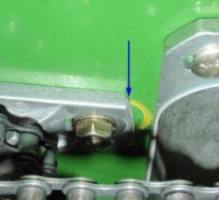
Chain-drive RowCommand and heavy-duty downforce
 Chain interference with heavy-duty downforce
As seen in the image, chain interference may result when operating chain-drive RowCommand on planters equipped with short and long parallel arms and heavy-duty downforce springs.
NOTE: Chain-drive RowCommand is only compatible with planters equipped with pneumatic downforce systems. On planters equipped with the heavy-duty downforce springs, potential chain interference may result and is not recommended.
Chain-drive RowCommand with corn finger pickup meters
 Bracket material removal
Due to the design characteristics of the chain-drive RowCommand clutch, some modification to the corn finger pickup meter drive bracket is required. As seen in the image above, some material needs to be removed from the front of the meter drive bracket in order for the chain-drive RowCommand clutch to have sufficient space for installation.
NOTE: Chain-drive RowCommand requires some modification to brackets in order to function with corn finger pickup meters.
RowCommand ordering information
To add RowCommand to a model year 2009 and newer planter model listed above is simple. Pro-Shaft drive attachments for field conversion and chain-drive attachments for field conversion are available by planter model to add the appropriate number of clutches, EPMs, brackets, hardware and row-unit harnesses. For complete installation and part detail for the RowCommand conversion, please use the RowCommand compatibility tool per specific planter model.
RowCommand is compatible and available for model year 2003 (serial number 700101) to 2008 (725101) planter models listed above. In addition to the attachment for field conversion attachment, a planter mainframe harness, SeedStar 2 controller (wedge box), and additional CAN harnesses are needed.
Integrated Section Control
Coupling RowCommand with Section Control provides the ultimate in precision planting and productivity. One company and one integrated solution are what John Deere offers by incorporating Section Control capabilities within the SeedStar 2 wedge box (controller). Unlike previous systems, no rate controller, additional harnessing, or components are required to achieve automated individual-row control.
SeedStar 2 and XP monitoring, RowCommand, and Section Control activation from John Deere Precision Ag Technologies are all that is needed when ordering.
System requirements
RowCommand is a simple and efficient means to control individual row planting using low-voltage electric clutches. When activated, each clutch consumes no more than 0.5 amps. By design, power is only supplied to the clutch when a signal is received to stop planting. In a normal planting condition, no power is supplied, and the clutch is de-energized.
Power for the RowCommand system is provided from the nine-pin ISO implement connector. All late-model 8X00 and 9X00 Series and newer John Deere Tractors equipped with the nine-pin ISO implement connector can supply ample power for system operation.
Along with ample system power, a GreenStar display and SeedStar monitoring are required for operation and control interface. The GreenStar display is where system setup, control settings, and manual control functions are performed.
Seed variable-rate drive (VRD) with half- or three-width disconnect
 VRD shown on a 1775NT
The seed variable-rate drive provides the ultimate planting productivity by utilizing one, two or three hydraulic motors (varies by model) to turn the seeding drive shaft. Hydraulic control of the seeding drive allows for on-the-go seeding rate changes right from the display mounted inside the tractor cab.
Combine this seeding flexibility with the map-based planting option, and seeding rates adjust automatically based on a prescription map.
Single- or dual-motor systems for variable-rate drives are available for all John Deere planters except the 1785 Rigid Frame. Dual- or three-motor drive systems are commonly used on larger (12-row and more) planters and offer the capability of half-width or three-section drive disconnect.
The VRD is available as a factory-installed option for all applicable planter models. Single- or dual-motor systems are available as field-installed attachments for most planter models; however, a three-motor VRD field-installed attachment is not available.
The seed VRD requires the SeedStar™ monitor and a radar input signal. Either tractor or planter radar may be used. Planter radar is ordered separately.
VRD offers the following advantages over common, contact-tire drive systems:
- Almost instantaneous rate changes – there is no ramp up or ramp down of system as in some competitive systems
- Permits the operator to match seed population based on different soil types or irrigation practices
- John Deere design that provides added operator safety by eliminating any possible drive creep found in some competitive variable rate drive systems
Half-width drive disconnect
The half-width drive disconnect feature is excellent for the producer concerned with controlling seed costs. This feature helps the operator place seed in the desired area and limit the amount of costly overlapped planting.
The half-width drive disconnect allows the operator to turn off half of the planter at a time for planting end rows, point rows, etc. Variable-rate-equipped planters require two drive motors to utilize the half-width disconnect feature.
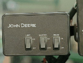
 Half-width drive disconnect within frame control
With a 1765, 1765NT, and 1775 12-Row Planter, a single switch box is required for planters that are ordered with variable rate drive and half-width disconnect.
For the 1775NT, 1775NT Central Commodity System (CCS™), and 1795 Front-Folding Planters, the half-width drive disconnect switch is contained within the frame control box, conveniently located in the tractor cab. The function easily shuts off the drive for the left or right half of the planter row-unit seed meters.
Three-width drive disconnect
 Three-width drive disconnect control
Three-width drive disconnect is an option on 1725 12-Row Planters and is base equipment on the 1725 16Row30 Planter. This feature is activated by three individual console mounted switches (control box), conveniently located in the tractor cab. The function easily shuts off the planter row-unit seed meters by one-, two-, or three-drive segments independently.
Drawbar hitch
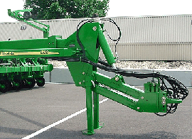 Drawbar hitch
A factory-installed, optional drawbar hitch is available for use with 1775NT 16- and 24-Row, 1775NT Central Commodity System (CCS™) 16- and 24-Row, and 12.2-m (40-ft) 1795 Planters. For all DB models the drawbar hitch is in base. All DB models are available with Category 5 drawbar hitch. The following DB models are not available with Category 4 drawbar hitch: DB80 48R20, DB88 48R22, DB90 36R30, DB90 54R20, and DB120 48R30.
The planter drawbar hitch provides easy operation with plenty of ground clearance. The hitch design utilizes a hydraulic cylinder to raise the planter hitch for transport. Hydraulic oil for the hitch cylinder on 1775NT and 1795 Planters comes from the row marker system. Activation of this cylinder is accomplished using a single switch on the display and the marker selective control valve (SCV).
Due to the hydraulic system design, the drawbar hitch requires the planter be equipped with independent markers (not tied to planter lift circuit). Removal of markers from all planters, except the 1775NT 24Row30, makes the drawbar hitch inoperable. The 1775NT 24Row30 is the only planter where the drawbar hitch, less markers, is a valid combination.
For planting on 38.1-cm (15-in.) row spacing with a 16/32-Row 1795 Planter, the drawbar needs to be offset 19-cm (7.5-in.) on the tractor to center the planting rows behind the tractor. When the 16/32 1795 has a drawbar hitch, operators may not be able to offset the hitch to the exact specifications of 19-cm (7.5-in.) when planting in 38.1-cm (15-in.) operation, and could be off as much as a 1.3-cm (0.5-in.). To compensate, additional adjustments to the marker will be necessary.
When using a guidance system such as parallel tracking or AutoTrac™ assisted steering system, operators will need to use their implement offset when planting with all rows on 1795 Planters equipped with the drawbar hitch to compensate for the offset.
The drawbar hitch is ideal for those who have 9000 Series Tractors without a 3-point hitch. For these, the planter drawbar hitch is the economical choice instead of adding a 3-point hitch.
To accept the planter drawbar hitch, the tractor drawbar must be ordered with, or upgraded to, a Category 4 drawbar with the heavy-duty package or Category 5 to be compatible. Track tractors with wide-swinging drawbars are not compatible with the planter drawbar hitch due to a lower hitch-load capacity.
Each 1795 or 1775NT Planter ordered with the drawbar hitch will be shipped with a Category 4 hitch link installed. A Category 5 hitch link is also shipped with the planter if the planter is to be used with a Category 5 drawbar. See pre-delivery instructions included with the planter for changeover information.
Compatibility:
- Category 5 implement hitch links are not compatible with Category 4 tractor drawbars.
- Category 5 tractor drawbars are not compatible with Category 4 implement hitch links.
This hitch also adds 0.6-m (2-ft) to planter length during transport and field operation. There are some combinations of planter options that are not compatible with the drawbar hitch option due to tractor drawbar limitations.
DB fertilizer options
Option code 2625 – Liquid fertilizer with row-unit mounted in-furrow applicator:
- This option contains a ground driven pump, plumbing to a manifold, and routing to each row-unit. The in-furrow applicator places fertilizer after the seed and before the closing wheels.
The DB60 24Row Split 47 Planter and DB60 24Row Split 48 Planter applies fertilizer on 76.2-cm (30-in.) row spacing only.
Central Commodity System (CCS™) seed delivery system
 CCS
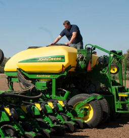
CCSCCS seed delivery adds productivity through increased seed capacity, bulk fill capability, and easy, thorough cleanout.
The two tanks have a combined capacity of 2466.7 L (70 bu) on 9.1-m (30-ft) planters and 3523.9 L (100 bu) on 12.2-m (40-ft) and larger planters. CCS tanks are manufactured using a rotomolded, polyethylene design to ensure maximum durability. The translucent tanks allow easily viewing the amount of seed in the tanks. The tanks are separated by 54.6 cm (21.5 in.) for enhanced rear visibility during transport and backing.
The following crops can be planted with CCS: corn, sweet corn, popcorn, cotton, sunflowers, sugar beets, soybeans, and sorghum (milo).
Filling the tanks is convenient due to a central filling location. The staircase and railing provide access to the filling platform between the tanks. If filling the tanks with an auger, minimum recommendations are a 15.2-cm (6-in.) diameter, 4.3-m (14-ft) auger. Each tank has an adjustable bin-level sensor to alert the operator when it is time to fill.
A standard fill light package is available on machines equipped with CCS. This feature includes two lights conveniently mounted on the railings of the machine. The lights are turned on and off with their own switch located at the bottom of the staircase.
If the seed-carrying vehicle requires hydraulic power to run the unloading system, the auxiliary hydraulic coupler option is available. These couplers are located at the bottom of the staircase and can be coupled under pressure. The system has a separate system filter that ensures the planter hydraulic system remains free of contaminates.
Seed delivery process
CCS is about reducing the time spent filling the planter with seed while maximizing the time spent planting. CCS for planters is a form of seed handling and delivery. The row-units perform the final task of seed metering and placement.
The CCS seed delivery process relies on a hydraulically driven fan to move seed from the CCS tanks to the row-unit hoppers. A flow control valve and gauge, located near the tank, allows for the proper tank pressure setting based on seed type. For normal operation, the CCS functions of fan and agitator control, as well as bin level sensing alerts, are controlled by status of the height switch. The CCS functions are enabled when the machine is lowered and disabled when the machine is raised. In addition, the CCS functions can be engaged for CCS hose cleanout using the switch on the back of the planter when oil flow is present. On models with software-based CCS control, CCS functions can be enabled or disabled through software interface in the cab as well as the switch on the back of the planter.
Air from the fan pressurizes the CCS tanks and delivers seed to the seed hoppers. Airflow enters the seed tanks through a nozzle in the manifold which pressurizes the tank. The air then picks up seed and moves it out the other end of the nozzle into seed delivery hoses. These hoses route the seed toward the hopper. A small amount of seed is traveling in the delivery hoses only when needed.
The hopper fills with seed until the delivery hose (discharge elbow) is covered. Once the opening is restricted, seed flow through the hose stops. Air flowing to the row-unit travels into the hopper and is the source of air for the vacuum system. This provides a much cleaner air source than previous meter designs. As the seed is picked up by the meter and planted, the seed pool shrinks until the end of the delivery hose is uncovered. At that time, the airflow and seed delivery resume and the seed pool in the hopper is replenished.
CCS tank scales for DB Planter models
The CCS tank scales for DB models are a stand-alone system from Digi-Star®. Load cells are installed at the factory and can be ordered for CCS or CCS with Refuge Plus.
There are three load cells, two at the rear of the CCS cradle and one at the front. They weigh both tanks as one; individual tank weights cannot be determined.
The load cells and display are made by Digi-Star. They are not on the controller aread network (CAN) bus system so they are not integrated into SeedStar™ software in any way. The monitor is sold separately through Digi-Star.
CCS seed cleanout
Seed cleanout could not be much easier with a CCS planter. When finished planting, any remaining seed can simply be removed via access doors at the bottom of the CCS tank.
Because seed is only traveling through the CCS delivery hoses when required by the meter, there is not much left to clean.
CCS seed delivery hoses are then purged with air from the CCS fan, and the excess seed is pushed to the individual meters. The vacuum meter door is opened and seed is removed with the supplied catch pan.
Small seed CCS components
 Manifold nozzle and nozzle with cover installed
 Straight seed inlet installed in mini-hopper
CCS seed delivery system increases planting productivity across the seven approved crops listed above. While highly effective delivering seed from the CCS tanks to the vacuum meters, small or light seeds (sorghum and small cotton) will require two additional components to aid in proper seed delivery.
Manifold nozzle covers (clips) should be installed to ensure seed is adequately picked up into the air stream for delivery to the row-unit. Mini-hopper discharge elbows should also be changed from the standard elbow (holes) to the small seed elbow (slotted openings) when planting sorghum (milo) and small cotton.
Digi-Star is a trademark of Digi-Star LLC.
Provide added versatility and productivity with Central Commodity System (CCS™) Refuge Plus planter configuration
DB44, DB60, DB60T, DB66, DB80, DB88, DB90, and DB120 Planters can be equipped with the Refuge Plus option from the factory.
The third tank on the Refuge Plus system provides increased versatility and productivity to the planting operation by allowing the grower to plant two different varieties simultaneously. The Refuge Plus tank has manifold nozzles, or outlets, to supply seed to eight different row-units.
Refuge Plus is ideal for the grower planting Bt corn or seed corn. Refuge Plus is the solution for refuge management compliance issues associated with Bt corn production. The 881-L (25-bu) capacity of the third tank makes planting the required 20 percent refuge of non-Bt corn easier while maintaining high productivity levels of the central-fill CCS.
For example, Bt corn planted on 80 percent of the field goes into the larger CCS tanks. The required 20 percent refuge, non-Bt corn, goes into the third Refuge Plus tank with the seed hoses routed to the desired rows.
Central fill with CCS is easier for the seed-corn grower as well. The seed-corn grower can plant both male and female seed in the desired pattern simply by placing the male seed in the Refuge Plus tank, the female seed in the CCS tanks, and routing the seed delivery hoses to the desired row units.
NOTE: Only DB44, DB60, DB60T, DB66, DB80, DB88, DB90, and DB120 Planters can be equipped with the Refuge Plus option from the factory. Other CCS equipped models can add Refuge Plus through Parts.
Redirecting seed delivery
 Seed delivery hose connection and yellow plug
Redirecting seed delivery from the CCS tanks to the Refuge Plus tank is fast and easy with quick-disconnect couplers. By simply disconnecting the desired CCS delivery hoses from beneath the CCS tank, capping those hoses and reconnecting the delivery lines to the Refuge Plus tank, the seed delivery source is changed.
Due to the additional weight Refuge Plus places on the planter frame, liquid fertilizer tanks are not compatible. Updated liquid insecticide tank codes have been established for Refuge Plus planters.
Take planter monitoring to the next level with SeedStar™ 3 HP monitoring system
SeedStar 3 HP overview
 SeedStar 3 HP shown on the GreenStar™ 3 2630 Display
Building upon the foundation of previous SeedStar monitoring, the SeedStar 3 HP monitoring system takes planter monitoring to the next level. When paired with the GreenStar 3 2630 Display, the SeedStar 3 HP monitoring system provides critical information about the planting process to the operator within the tractor cab. SeedStar 3 HP is compatible with the GreenStar 3 2630, the Gen 4 4200 CommandCenter™ Display, the Gen 4 4600 CommandCenter Display, the 4240 Universal Display, and the 4640 Universal Display.
Detailed planter performance information allows the operator to make adjustments needed for planter optimization. After all, with rising costs, it is imperative to make sure that every seed is planted accurately and precisely within the seed furrow for maximum yield potential.
The SeedStar 3 HP planting functions are fully integrated with the full spectrum of Precision Ag Technology applications such as John Deere Section Control for Planters, GreenStar 3 2630 Display, AutoTrac™ assisted steering system, John Deere Operations Center, JDLink™ telematics system, and others. Integrated planting technologies, for better asset utilization and ease of use, is just part of what SeedStar 3 HP provides.
SeedStar 3 HP main run page
 SeedStar 3 HP main run page
SeedStar 3 HP has an updated main run page layout. With the use of tabs toward the top of the screen it is much easier to navigate through readings such as population, singulation, spacing, downforce, and ride quality. If for some reason an issue arises with a row-unit, the tab will turn red indicating there is an issue. The tab can be pushed and lead to what is causing the issue. Inside each tab, there will be a bar graph detailing information specific to that tab. The picture shows what a population bar graph looks like. This layout improves functionality and overall ease of use while planting.
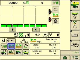
SeedStar 3 HP seed singulation monitoring
 SeedStar 3 HP seed singulation planter run page
Understanding meter singulation performance on the planter is critical to minimizing the amount of seed multiples and skips. As a result, the SeedStar 3 HP monitoring system provides real-time information, from the redesigned seed sensors placed in each brush belt cartridge, about the overall seed singulation performance.
As seen in the screen shot image above, overall singulation performance is seen in the tab at the top of the screen. Seed skip and multiple sources of information are displayed below the bar graph of the run page. This provides the operator a better understanding of relative seed multiple and skip data on a row-unit basis within one easy glance at this run page.
Also, within the seed singulation planter run page, information about row-units with the highest percentage of seed multiples and skips is provided in order to make necessary adjustments for better planter optimization.
SeedStar 3 HP row-unit downforce planter run page
 SeedStar 3 HP downforce planter run page
With changing field conditions, it is important to monitor down force to ensure consistent seed placement. Seeds placed too shallow or too deep can impact emergence and affect yield.
With the SeedStar 3 HP monitoring system, row-unit downforce information is measured by the downforce sensor and sensor and transmitted to the GreenStar display in the tractor cab. The row-unit downforce information is displayed on the top portion of this run page with more row-unit downforce information on the lower portion.
Active downforce takes SeedStar 3 HP even further by removing constant downforce adjustments from the operator and actively controlling the downforce system to maintain a desired target margin. Just set the row-unit target margin value and the active downforce system works automatically to make sure the planter maintains this value-achieving, precise soil penetration and consistent planting depth without sidewall soil compaction. This frees the operator from constantly making manual downforce adjustments as conditions change.
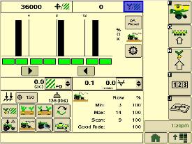
SeedStar 3 HP ride quality and ground contact run page
 SeedStar 3 HP ride quality and ground contact run page
The fifth tab from the left in SeedStar 3 HP is a shared tab between ground contact and ride quality. Operators may change between the two criteria based on their planter setups or personal preferences. Ground contact displays the percentage of time the row-units are engaging the ground, the load is measured via a sensor through the gauge wheels. Ground contact is recommended to ensure the row-unit is maintaining proper depth at higher planting speeds.
SeedStar 3 HP seed spacing monitoring
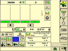
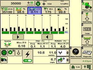 SeedStar 3 HP seed spacing planter run page
Throughout the planting process, obtaining good seed spacing is critical towards achieving plant growing conditions for maximum yield potential.
Today, many items are adjusted on the planter prior to planting to optimize overall seed spacing performance. But after such adjustments are made, information about the actual seed spacing performance during planting was missing within the planter monitoring system. With SeedStar 3 HP, seed spacing information is transmitted live via the GreenStar display to show the operator exactly what is happening with the planter behind them.
The SeedStar 3 HP transmits seed spacing information onto the bar graph (shown above) for easy understanding of planter seed spacing performance. Also, information about seed skips and multiples are provided to help understand actual planter meter performance and other related system functions in order to make necessary adjustments if needed.
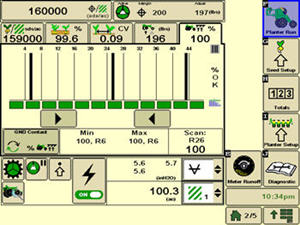
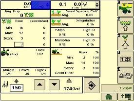
SeedStar 3 HP meter runoff page
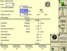 SeedStar 3 HP runoff page
On SeedStar 3 HP, the meter runoff page allows growers to test meters before going to the field. Growers can now test the meters without removing them and have confidence in their planter’s performance before going to the field. Many parameters can be viewed during this test such as: singulation, seed count, skips, multiples, coefficient of variation (cv), etc. This test assures that the meter is in healthy condition and ready to plant when conditions are appropriate.
Other SeedStar 3 HP monitoring features include:
- Capable of monitoring individual row-unit and overall planter performance in terms of seed spacing, singulation, and row-unit downforce
- On-screen indication of down force sensor assemblies once configured within the monitor settings application
- Full-color display icons for easy recognition and overall aesthetics
- Downforce system controls with the GreenStar display application
- A run page that allows operator to view relative population levels of all rows on one screen
- Mapping of actual and target seed rates can be mapped in Operations Centers.
- Reprogrammable utilizing controller area network (CAN) via Service ADVISOR™ diagnostics system or Service ADVISOR Remote with JDLink connectivity
- User-configurable high fertilizer pressure alarm that allows the operator to be warned when fertilizer pressure reaches a specific level
- Automatic Fast Start for SeedStar 3 HP ensures that seeds will be place accurately when starting from a stop.
- Automatic tractor speed source selection. When equipped with an 8000/9000 Series Tractor, the system selects the radar speed or allows for manual speed input selection.
Components and operation
 Planter main controller
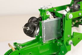 Row-unit controller (RUC) with two electric motors
The SeedStar 3 HP monitoring system contains the following components in order to support the planting data transfer to the GreenStar displays:
- Planter main controller
- Downforce sensor assembly
- Electric power gen (EPG)
- Row-unit controller (RUC)
The row-unit controller processes the row-unit data from the sensor node assemblies located on the row-unit head casting. The processed information is then sent to the planter main controller to be integrated into the displayed information being sent to the GreenStar display.
Downforce sensor assemblies are found on row-units with sensor installed. The downforce sensor assembly is put together with the gauge wheel depth-adjustment handle and provides gauge wheel pressure information to the respective sensor node for data processing.
 Downforce sensor installed
 Downforce sensor
Depending on the planter size, different configurations of sensor and downforce sensors are installed in support of the SeedStar 3 HP monitoring system.
SeedStar™ XP monitoring system
SeedStar XP overview
 SeedStar XP shown on the GreenStar™ 3 2630 Display
 SeedStar XP shown on the GreenStar 2 1800 Display
Building upon the foundation of SeedStar 2, the SeedStar XP system takes planter monitoring to the next level. SeedStar XP is compatible with the GreenStar 2 1800 and 2600 Displays, GreenStar 3 2630 Display, the Gen 4 4200 CommandCenter™ Display, the Gen 4 4600 CommandCenter Display, the 4240 Universal Display, and the 4640 Universal Display. SeedStar XP is not compatible with the Gen 4 Extended Monitor.
Specific information about how the planter is performing enables the operator to make needed adjustments for implement optimization.
The SeedStar XP planting functions are fully integrated with the full spectrum of Precision Ag Technology applications such as Swath Control Pro™ system for planters, Section Control, GreenStar AutoTrac™ assisted steering system, John Deere Operations Center, Documentation, and others. Integrated planting technologies for better asset utilization and ease of use is just part of what SeedStar XP provides.
SeedStar XP seed singulation monitoring
 SeedStar XP seed singulation planter run page
Understanding the meter singulation performance on the planter is critical to minimizing the amount of seed multiples and skips. As a result, the SeedStar XP monitoring system provides real-time information from the row-units about the overall seed singulation performance.
As seen in the screen shot image above, seed multiple information is displayed on the top portion of the planter-at-a-glance bar with seed skip information on the lower portion. This provides the operator a better understanding of relative seed multiple and skip data on a row-unit basis, all within one easy glance.
Also, within the seed singulation planter run page, information about row-units with the highest percentage of seed multiples and skips is provided in order to make necessary adjustments for better planter optimization.
SeedStar XP row-unit ride dynamics planter run page
 SeedStar XP ride dynamics planter run page
While operating a planter, travel speed and field conditions can affect the amount of row-unit bounce that is experienced. Excessive row-unit bounce or vertical motion can cause problems with meter performance. To better understand the amount of row-unit vertical motion when travelling through a field, the SeedStar XP monitoring system provides real-time information on row-unit ride dynamics.
As seen in the ride dynamics planter-at-a-glance screen shot image above, the SeedStar XP system provides ride dynamic information for each sensor node that is mounted on the planter. Each sensor node transmits ride dynamic information for each planter frame section to allow for the operator to make necessary operating adjustments to improve overall planting performance.
SeedStar XP row-unit downforce planter run page
SeedStar XP downforce planter run pageAs row-unit downforce systems gradually change from heavy-duty downforce springs to pneumatic downforce, being able to understand the amount of as-applied row-unit downforce is needed while operating the planter.
With various soil conditions, moisture, etc. experienced while planting, it is imperative to have the ability to change actual row-unit downforce to have enough force for the Tru-Vee openers to penetrate the soil media. However, in some conditions, having too much downforce applied to the row-units for effective opener penetration could cause problems with side wall compaction from the gauge wheel.
Side wall compaction within the seed furrow can cause hatchet roots to develop, or roots that do not have the ability to penetrate the seed furrow soil media. This could lead to poor plant emergence and eventually lower overall yield performance.
With the SeedStar XP monitoring system, row-unit downforce information is measured by the downforce sensor and sensor nodes and transmitted to display in the tractor cab (as seen in the image above). The row-unit downforce information is displayed on the top portion of the planter-at-a-glance bar with more row-unit downforce information on the lower portion.
Two different control options are available on 1775NT, 1795, and DB Series Planters for pneumatic downforce. The base pneumatic downforce system requires manual control of the downforce to maintain the desired planting results or row-unit margin. Optional active pneumatic downforce takes SeedStar XP even further by removing constant downforce adjustments from the operator and actively controlling the downforce system to maintain a desired target margin.
The 1745 Planter with pneumatic downforce and SeedStar XP will require manual control of the downforce to maintain row-unit margin.
SeedStar XP seed spacing monitoring
 SeedStar XP seed spacing planter run page
Throughout the planting process, obtaining good seed spacing is critical toward achieving plant growing conditions for maximum yield potential.
Today, many items are adjusted on the planter prior to planting to optimize overall seed spacing performance. After such adjustments are made, information about the actual seed spacing performance during planting was missing within the planter monitoring system. With SeedStar XP, seed spacing information is transmitted live via the GreenStar display to show the operator exactly what is happening with the planter behind them.
The SeedStar XP transmits seed spacing information onto the planter-at-a-glance bar for easy understanding of planter seed spacing performance. Also, information about seed skips and multiples is provided to help understand actual planter meter performance and other related system functions in order to make necessary adjustments if needed.
NOTE: Seed spacing and seed singulation information is only available when planting crops with seed drop rates below 40 seeds per second such as corn. With higher population crops such as soybeans the system does not provide spacing and singulation information because the number of seeds dropping per second is much higher.
SeedStar XP full planter performance page
 SeedStar XP planter details
 With the capability of monitoring differences in planting performance items such as seed singulation and row-unit downforce, having one screen to view all planter performance elements is needed to understand the whole planting system. SeedStar XP combines all of the various planting performance elements into one full-color, planter overview screen to enable for a quick understanding of relative planting functionality.
SeedStar XP half screens and other features
 SeedStar XP seed singulation half screen
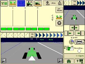 SeedStar XP seed spacing half screen
Other SeedStar XP monitoring features include:
- Capable of monitoring individual row-unit and overall planter performance in terms of seed spacing, singulation, and row-unit downforce
- Split-screen applications to enable use of popular guidance features such as AutoTrac assisted steering system
- On-screen indication of sensor node/downforce sensor assemblies once configured within the monitor settings application
- Full-color display icons for easy recognition and overall aesthetics
- Pneumatic downforce system controls with the GreenStar display application
SeedStar 2 monitoring original features
SeedStar XP retains all of those SeedStar 2 features that producers value and have come to expect:
- Planter-at-a-glance – allows operator to view relative population levels of all rows on one screen.
- Automatic valve calibration – with the SeedStar variable-rate drive (VRD), this is completed automatically. There is no longer a need to manually calibrate the hydraulic valves.
- Increased population updates – SeedStar will update population levels once per second at planter start up then approximately once every three seconds.
- Mapping of actual seed rates – when combined with documentation, actual and target seeding rates can be mapped in John Deere Operations Center.
- Reprogrammable utilizing controller area network (CAN) via Service ADVISOR™ diagnostics system.
- Improved diagnostics/event recorder – on SeedStar VRD planters, additional diagnostic information is available, as well as an event recorder to capture system performance data at a specific point in time.
- Ability to run motors at different population levels – on SeedStar VRD, operators running multiple motor systems can run each motor at a different speed, allowing different population levels within a planter.
- User-configurable high fertilizer pressure alarm – allows the operator to be warned when fertilizer pressure reaches a specific level.
- Automatic quick-start for SeedStar VRD – no longer does the operator need to press the quick-start button on end row turns to resume planting.
- Automatic tractor speed source selection – when equipped with an 8000/9000 Series Tractor, the system selects the radar speed or allows for manual speed input selection.
Components and operation
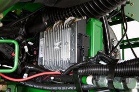 Planter main 2 controller
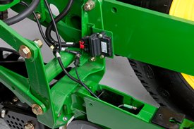 Sensor node assembly installed
The SeedStar XP monitoring system contains the following components in order to support the planting data transfer to the GreenStar 2 Displays:
- Seed monitor/variable-rate (SMVR) controller with model year 2011 or newer software
- Planter main 2 controller (installed on all SeedStar XP eligible models for model year 2011 or newer)
- Sensor node(s)
- Downforce sensor assembly
The planter main 2 controller processes the row-unit data from the sensor node assemblies located on the row-unit head casting. The processed information is then sent to the SMVR controller to be integrated into the displayed information being sent to the GreenStar Display.
Downforce sensor assemblies are found on row-units with sensor nodes installed. The downforce sensor assembly is assembled with the gauge wheel depth-adjustment handle and provides gauge wheel pressure information to the respective sensor node for data processing.
 Downforce sensor installed
 Downforce sensor assembly
Depending on the planter size, different configurations of sensor nodes and downforce sensors are installed in support of the SeedStar XP monitoring system.
Specifications
Key Specifications
- Frame Fold Configuration
- Front fold
- Hitch Base
- Drawbar
- Tyres Quantity
- 8
- Markers Type
- Tri-fold

We have a range of finance options to suit any customer. Contact your local Emmetts branch, or visit these sites for more information and a free quote.