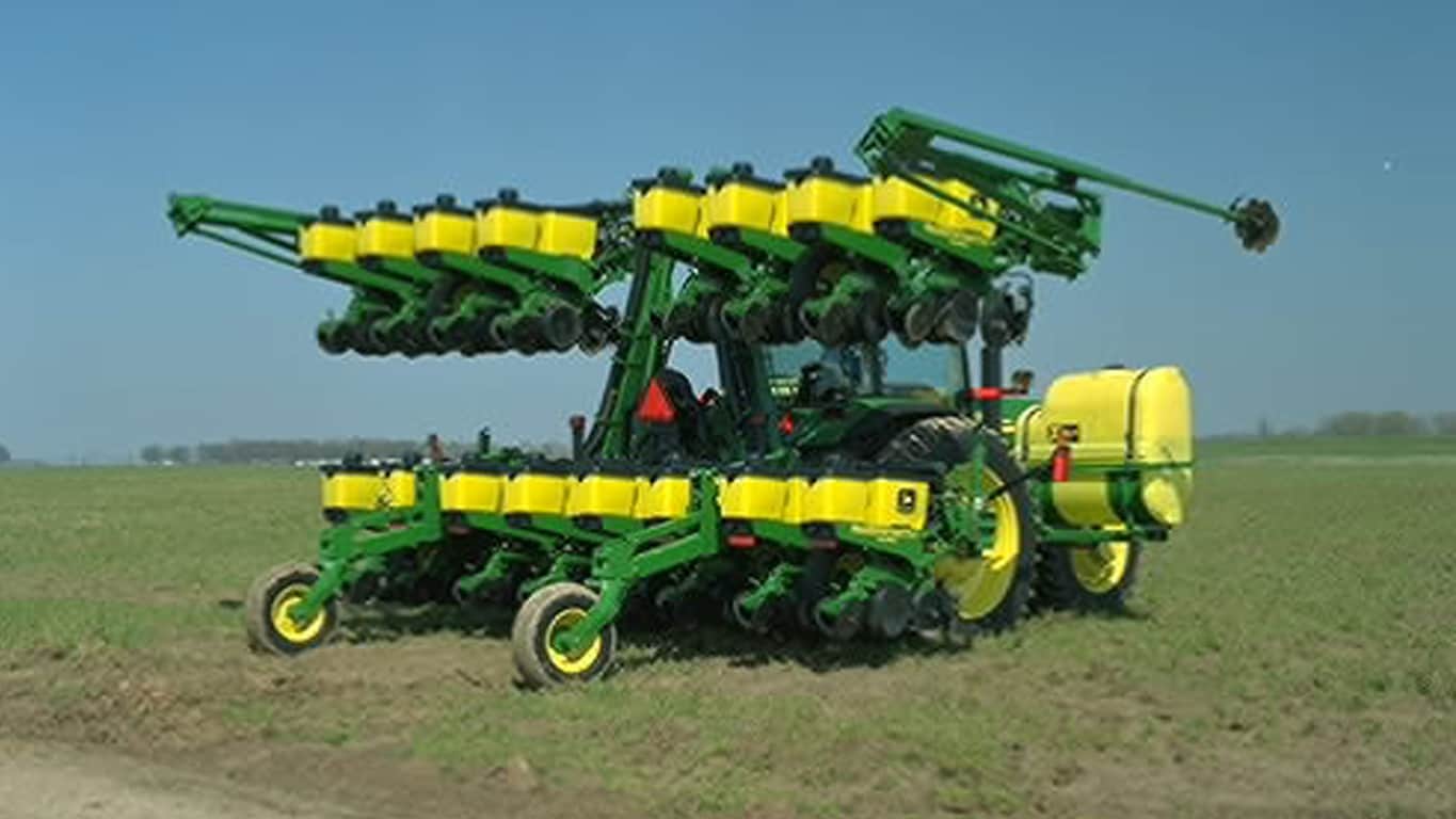
- Offered in 8-, 12-, or 16-row configuration
- Row spacing options include 914 mm (36 in.), 965 mm (38 in.), and 1,016 mm (40 in.) for 8- and 12-row frames, and 762 mm (30 in.) spacing for 12- and 16-row frames.
- Available in 1.6 bu. or 3 bu. MaxEmerge™ 5 row unit
- Insecticide option for 1.6 bu.
Features
RowCommand™ individual-row control system
RowCommand controls seed output
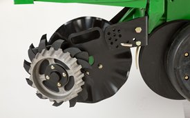
 RowCommand on a MaxEmerge™ 5 row-unit
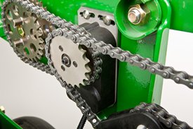 RowCommand on a chain drive MaxEmerge 5 row-unit
Controlling input costs and improving productivity are key producer requirements today. RowCommand is an effective, integrated John Deere solution designed to meet these intensifying needs. The RowCommand system manages seed output, reduces yield drag, and improves harvest capabilities on all Pro-Shaft™ driven row-units, and chain-driven MaxEmerge 5.
NOTE: Chain-drive RowCommand is only compatible with planters equipped with pneumatic downforce systems. On planters equipped with the heavy-duty downforce springs, potential chain interference may result and is not recommended.
NOTE: Chain-drive RowCommand requires some modification to brackets in order to function with corn finger pickup meters. Information on the modifications needed is found in the following sales material.
NOTE: Pro-Shaft drive RowCommand is compatible on MaxEmerge 5 row-units with vacuum and corn finger pickup meters. For mini hopper row-units, RowCommand is compatible on vacuum meters only and is not compatible on corn finger pickup meters. There is a select group of planters that might have Pro-Series XP row-units with corn finger pickup meters in which RowCommand will not be compatible.
RowCommand controls seed output by incorporating individual, low amperage clutches inside the Pro-Shaft and chain-driven gearboxes. Clutches are completely enclosed within the gearbox housing to protect them from the elements and harsh operating conditions.
When power is supplied, either manually or through Swath Control Pro™ system, clutches disengage the seed meters and seed flow stops. Controlling seed output at individual rows reduces overplanting in point rows and maximizes seed placement when entering/exiting headlands.
Components and operation
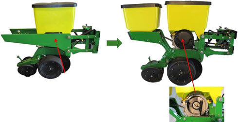
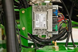 EPMs shown on a 1775 NT Planter
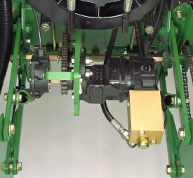
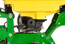 RowCommand clutch on MaxEmerge 5 with 3 bu hopper
RowCommand is a simple and efficient solution to control individual row planting. This system does not utilize air to operate; therefore, no compressor, entangling air lines, or valve modules are required.
RowCommand utilizes low-voltage controller area network (CAN) messaging to signal power to the desired clutches to stop planting or eliminates power to resume planting.
This means very little power is used in normal planting conditions, and in the event a clutch fails electrically, the meter will continue to plant.
The RowCommand system requires the following five basic components to operate:
- Electric clutches
- Electronic power modules (EPMs)
- SeedStar™ 2 monitoring (wedge box/controller)
- GreenStar™ (GS) 2 Display
- Planter wiring harnesses
Clutches are protected within the sealed Pro-Shaft and chain-driven gearboxes for years of trouble-free operation and simple installation or removal. RowCommand has true individual-row control of up to 16 clutches or sections for planters larger than 16 rows.
Unique to RowCommand, the 16 available control sections can be configured based on operator preferences. For example, on a 1775 NT 24-Row Planter, every two rows can be paired together for a total of 12 control sections, or control the outermost eight rows individually and the remaining inner rows paired together for 16 control sections. No other system can match this flexibility.
While SeedStar 2 with RowCommand has 16 control sections, a minimum of 152-cm (60-in.) wide sections are recommended for optimum Swath Control Pro capabilities. As with other Swath Control Pro products, a StarFire™ 2 signal is the minimum level of accuracy recommend for operation.
Integrated Swath Control Pro™
Coupling RowCommand with Swath Control Pro provides the ultimate in precision planting and productivity. One company, one integrated solution are what we offer by incorporating Swath Control Pro capabilities within the SeedStar 2 wedge box (controller). Unlike previous systems, no rate controller, additional harnessing, or components are required to achieve automated individual-row control.
SeedStar 2 monitoring, RowCommand, and Swath Control Pro activation from Ag Management Services (AMS) are all that is needed to reap the benefits of this technology. A single Swath Control Pro activation can now be leveraged across sprayers, nutrient applicators, planters, and air seeders.
Pro-Shaft drive RowCommand planters
RowCommand is available as a factory-installed option or as an attachment for field conversion attachments for the following Pro-Shaft drive planter models (see chart below).
| Planter model | Row configuration |
| 1725 | 12-row narrow, 12-row wide, and 16-row narrow |
| 1725 CCS™ | 16-row narrow |
| 1765 | 12-row narrow |
| 1775 | 12-row narrow |
| 1775NT | 12 row, 16 row, and 24-row narrow |
| 1775NT CCS | 12 row, 16 row, and 24-row narrow |
| 1795 | 12/23 row, 12/24 row, 16/31 row, and 16/32 row |
| 1795 | 24 row, 50 cm (20 in.) |
| DB 44 | 24 row, 56 cm (22 in.) |
| DB 58 | 32 row, 56 cm (22 in.) |
| DB 60 | 36 row, 50 cm (20 in.) or 47 row, 38 cm (15 in.) |
| DB 66 | 36 row, 56 cm (22 in.) |
| DB 80 | 32 row, 76 cm (30 in.) or 48 row, 50 cm (20 in.) |
| DB 88 | 48 row, 56 cm (22 in.) |
| DB 90 | 36 row, 76 cm (30 in.) |
| DB 120 | 48 row, 76 cm (30 in.) |
DR (Deere/Orthman®) 16R40 | 16 row, 102 cm (40 in.) |
| DR (Deere/Orthman) 18R38 | 18 row, 97 cm (38 in.) |
Chain drive RowCommand planters
In terms of planter compatibility, RowCommand for chain drive is designed for the following planter model configurations equipped with pneumatic downforce systems.
| Planter model | Row configuration |
| 1725 | 12-row narrow, 12-row wide, and 16-row narrow |
| 1765 | 12-row narrow |
| 1775 | 12-row narrow |
| 1775NT | 12 row, 16 row, and 24-row narrow |
| 1775NT CCS | 12 row, 16 row, and 24-row narrow |
| DB 44 | 24 row, 56 cm (22 in.) |
Chain drive RowCommand and heavy-duty downforce
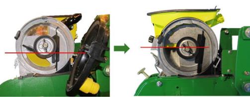
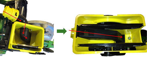
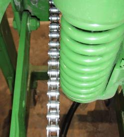 Chain interference with heavy-duty downforce
As seen in the picture to the left, chain interference may result when operating chain drive RowCommand on planters equipped with short- and long- parallel arms and heavy-duty downforce springs.
NOTE: Chain drive RowCommand is only compatible with planters equipped with pneumatic downforce systems. On planters equipped with the heavy-duty downforce springs, potential chain interference may result and is not recommended.
Chain drive RowCommand with corn finger pickup meters
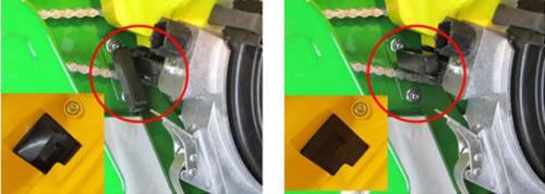
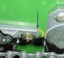 Bracket material removal
Due to the design characteristics of the chain drive RowCommand clutch, some modification to the corn finger pickup meter drive bracket is required. As seen in the picture to the left, some material needs to be removed from the front of the meter drive bracket in order for the chain drive RowCommand clutch to have sufficient space for installation.
NOTE: Chain drive RowCommand requires some modification to brackets in order to function with corn finger pickup meters.
RowCommand ordering information
To add RowCommand to a model year 2009 and newer planter model listed above is simple. Pro-Shaft drive attachments for field conversion and chain drive attachments for field conversion are available by planter model to add the appropriate number of clutches, EPMs, brackets, hardware and row-unit harnesses. For complete installation and part detail for the RowCommand conversion, please use the RowCommand Compatibility Tool per specific planter model.
RowCommand is compatible and available for model year 2003 (serial number 700101) to 2008 (725101) planter models listed above. In addition to the attachment for field conversion attachment, a planter mainframe harness, SeedStar 2 controller (wedge box), and additional CAN harnesses are needed.
System requirements
RowCommand is a simple and efficient means to control individual row planting through the use of low-voltage electric clutches. When activated, each clutch consumes no more than 0.5 amps. By design, power is only supplied to the clutch when a signal is received to stop planting. In a normal planting condition, no power is supplied and the clutch is de-energized.
Power for the RowCommand system is provided from the 9-pin ISO implement connector. All late-model 8X00 and 9X00 Series John Deere Tractors equipped with the 9-pin ISO implement connector are capable of supplying ample power for system operation.
Along with ample system power, a GS 2 Display and SeedStar 2 monitoring are required for operation and control interface. The GS 2 Display is where system setup, control settings, and manual control functions are performed.
Row cleaner options to meet residue management needs
As crop yields have increased over the years, so has the amount of residue left in the field after harvest. At the same time tillage practices have changed, including different tillage operations which maintain large amounts of surface residue, and even no till practices. Row cleaners are an essential tool in managing this increased amount of residue.
John Deere Seeding Group offers a variety of row cleaner options to meet the needs of a producer's operation. Compatibility varies by model, row spacing, and other planter equipment.
Screw-adjust unit-mounted row cleaner
 Screw-adjust unit-mounted row cleaner
The screw-adjust unit-mounted row cleaner is mounted directly to the face plate of the row unit, placing the ground engaging components just in front of the row unit opener blades and depth gauge wheels. This close proximity allows the gauge wheels to control the depth of the row cleaner as well as the row unit. This compact design also allows greater compatibility with fertilizer openers and other planter attachments.
SharkTooth® wheels are standard equipment on the unit-mounted row cleaner. The swept-tooth design of the wheel provides a clear path for the row unit openers while resisting residue buildup on the wheel. The screw adjustment knob is accessible through the top of the parallel arms, providing convenient access for adjustments. The row cleaner can be adjusted in 1/16-in. increments, providing plenty of flexibility to meet the needs of changing conditions.
Floating row cleaner with unit-mounted coulter
 Floating row cleaner with unit-mounted coulter
The floating row cleaner allows a row cleaner to be used in conjunction with a unit-mounted coulter. This combination is often desired in heavy residue loads and tough reduced tillage planting conditions. The row cleaner provides a clear path for the row unit, while the unit-mounted coulter helps penetrate tough soil conditions.
Accommodating the unit-mounted coulter means the residue wheels are farther forward from the row unit face plate than in the case of the screw adjust row cleaner. To maintain performance, this row cleaner has the capability to float above a defined minimum depth.
Standard depth-gauging bands on the wheels allow the row cleaner wheels to float independently of the row unit openers, allowing both to perform in varying terrain. The unit may also be set in a fixed position by simply pinning through the bracket if desired. This row cleaner also features SharkTooth wheels as standard equipment.
The floating row cleaner and unit-mounted coulters are available on many planters as factory-installed equipment. As compatibility and details vary by model, review the following links for information on specific planter models.
SharkTooth is a trademark of Yetter Manufacturing.
Improved pneumatic downforce system
Pneumatic downforce provides convenient, simple adjustment of downforce for the whole planter from one location. The amount of downforce applied is infinitely adjustable from 0 kg to 181.80 kg (0 lb to 400 lb). Pneumatic downforce provides more consistent downforce throughout the range of row-unit travel than mechanical spring downforce systems.
For model year 2011, several pneumatic downforce system improvements were implemented. Such improvements are:
- 3/8-in. air delivery line instead of the 1/4-in. line used on model year 2010 and older planters.
- Improved air compressor assembly increased duty cycle. With this new compressor, it provides a 47-percent increase in maximum air flow delivery compared to the prior air compressor.
- New pneumatic air bags with 3/8-in. air line inlets that have improved connecting points for greater durability.
Such improvements to the pneumatic downforce system will enable for faster and more precise control of row-unit downforce while planting.
System features
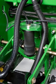 Pneumatic downforce spring
Each row-unit has a single, rubber air bag located between the parallel arms. The air bags are hooked in parallel so that air can be added or released from all rows at once from one location.
Pneumatic downforce systems are available as base equipment on all 1700 Series and Deere-Bauer planters. The individual pneumatic downforce air bag assemblies, air compressor units, and 3/8-in. delivery lines are also available as an attachment for field conversion.
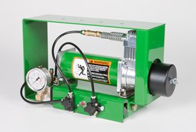 Pneumatic downforce compressor and gauge
An improved compressor is used to charge the pneumatic system. This compressor can be located on the planter frame or in the tractor cab if desired. A gauge at the compressor indicates the amount of downforce being applied.
From the factory, integral planter models with pneumatic downforce will have an improved air compressor assembly with an in-cab mounting bracket, except the 1725 16-row and 1725 Central Commodity System (CCS™ ) TR Planters will have the air compressor assembly mounted on the planter frame. For drawn planter models, the 1755, 1765, 1765NT, 1775 Front-Fold, and 1785 Drawn Planters will have the air compressor assembly installed either on the outer hitch or wing frame members when the pneumatic downforce system is installed.
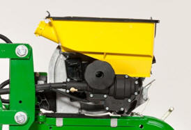
MaxEmerge™ 5
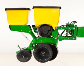 MaxEmerge 5 with 56-L (1.6-bu) hopper plus insecticide
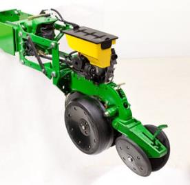 MaxEmerge 5 with mini hopper
The MaxEmerge family of row-units have never seen a more versatile and efficient design until the MaxEmerge 5. The 5-family row-units improve productivity, increase uptime and lower the cost of ownership like never before. Producers now have that all-in-one meter and row-unit straight out of the factory with one order, increasing their bottom line.
The MaxEmerge 5 row-unit looks distinctively different than previous MaxEmerge products. The changes were not done just for better looks, what was already an industry-leading row-unit in performance and serviceability just got even better.
The field-proven designs of both the MaxEmerge XP and Pro-Series XP™ were combined into one interchangeable meter design. Advanced manufacturing technology and world-class testing techniques were used to design a planter row-unit that has increased strength and longer-wearing parts, plus is easier to service, decreasing downtime during the grower’s most crucial season.
Serviceability and changing crops has always been a focus of downtime and potential seed loss. MaxEmerge XP Row-Units (shown on the left) are designed with the meter and hopper as one component. The frame covers the meter so that it cannot be accessed. Cleanout of excess seed requires the operator to take the entire hopper off of the row-unit and to turn it upside down. The MaxEmerge 5 meter (shown on the right) is accessible without having to remove the box. The MaxEmerge 5 design allows large hoppers to be cleaned out the same as mini-hoppers, simply by opening the meter dome and catching the seed as it falls out. This nice improvement will allow operators to change seed varieties easier and three times faster than it took them on the previous MaxEmerge XP units and provide more uptime during the tight planting window.
 MaxEmerge 5 meter shape
The MaxEmerge 5 meter shape has also been redesigned for better seed flow. The model year 2014 and older mini-hopper is starved of seed when operating on side-hills greater than 9 degrees. The enhancements made to the mini-hopper design with this program allow the planter to successfully operate on side hills up to 14 degrees. This correlates to the planter able to run on a 55 percent greater slope without loss in meter performance.
 Hopper shutoff
Also, to help with meter access of 56-L and 106-L (1.6-bu and 3-bu) hoppers the hopper shutoff feature was added. With the shutoff engaged, the meter cover can be opened without first having to remove all of the seeds from the hopper. Lever down, the seed flow is on, lever horizontal and the seed flow is off.
 MaxEmerge 5 mini-hopper
There are significant changes to the MaxEmerge 5 Mini-Hopper. One update is to the straight feed from the Central Commodity System (CCS™) hose to the mini-hopper to ensure a continuous free flow of seeds. As seed size and treatment grow, producers will not experience potential plugging issues. And inside the meter, the air is cleaner than ever because the vacuum air source has been changed, drawing from inside the CCS tank where there is far less debris. Cleaner meters lead to higher planting performance.
 Ductile iron-cast shank
The shank of the row-unit is the foundation of planter performance. All ground-engaging functions of the row-unit radiate from it.
The shank must be a pillar of strength and must not bend or twist under load. The perfect seed furrow, precision seed spacing, and alignment of the closing systems all depend on the row-unit shank being rock solid. The row-unit shank must have the strength to plant in all field conditions, acre after acre, year after year.
It all starts with the ductile iron-cast shank. Ductile iron casting is a unique high-tech process that produces a single-piece row-unit shank that replaces the traditional 13-piece welded shank.
The properties of ductile iron castings are such that they deflect without bending, withstand great impact without cracking, and can be machined to close tolerances for precise alignment of mating components perfect properties for a row-unit shank.
A ductile iron-cast shank is a foundation of higher quality and higher strength for a John Deere row-unit.
The row-unit head is also designed using the ductile iron-casting process. The row-unit head provides the mating joint between the row-unit parallel arms and the row-unit shank. It is also the upper attaching point for the seed meter and seed hopper.
Ductile iron casting of the row-unit shank and head assembly provides a row-unit that is 25 percent stronger than welded row-units.
In addition to strength, the cast shank also promotes better alignment of all row-unit components. The one-piece casting with its machined surfaces eliminates the variable tolerances associated with welded assemblies. Properly aligned components not only function better in the field, they also have a longer wear life.
The lower portion of the MaxEmerge 5 ductile iron shank incorporates a bayonet-style mount for the seed tube guard, offering greater ease of service. Simply slide the guard onto the bayonet mount with a quick twist and lock to attach the guard. Once the opener blades are in place, the seed tube guard is in position, ready for the seed tube.
 Tru-Vee opener blades and bearings
One of the trademark capabilities of John Deere planters has always been the ability of the Tru-Vee™ openers to provide a perfect seed furrow acre after acre in all types of field conditions.
The MaxEmerge 5 row-unit builds on this tradition with components that offer a longer wear life and reduced maintenance time, and provide value to the grower in reduced cost of ownership over the life of the planter.
The thickness of the Tru-Vee opener blades was increased from 3.0 mm to 3.5 mm (0.12 in. to 0.14 in.) with the introduction of the XP row-units and maintained with MaxEmerge 5. This increased opener blade thickness will provide 20 percent longer wear life.
The MaxEmerge 5 row-unit also provides better Tru-Vee opener bearings for longer life. The double-row ball bearing provides up to three times the wear life as the single-row bearing.
To complete the world-class Tru-Vee opener assembly, the rivets that secure the bearing and hub to
Performance | Uptime | Cost of operation |
|
|
|
 Depth adjustment T-handle
John Deere planters provide consistent seed depth control in all field conditions. Depth control is a function of the Tru-Vee openers, the downforce system, and the gauge wheel assembly.
The gauge wheel itself is made of durable nylon composition with a concave profile. This profile gently firms the sides of the seed furrow, ensuring a well-defined trench. The concavity also reduces rocks and residue being picked up and thrown onto the drive chains and row-units, and helps to prevent rooster tailing of soil.
The bolt-through design utilizes an open bearing in the gauge wheel that allows an attaching bolt to pass through the wheel to the threaded hole in the gauge wheel arm. This simple bolt-through design provides for a positive attachment of the gauge wheel to the gauge wheel arm and allows quick removal of the gauge wheel for service.
Adjustability of the row-unit is critical to good performance. MaxEmerge 5 row units are the most user-friendly, adjustable units in the industry.
- More available downforce options than any row unit in the industry
- Single downforce springs, non-adjustable, 41 kg (90 lb) of downforce
- Double downforce springs, non-adjustable, 82 kg (180 lb) of downforce
- Adjustable heavy-duty downforce, four settings, 0 kg (0 lb), 57 kg (125 lb), 113 kg (250 lb), and 181 kg (400 lb) of downforce
- Pneumatic downforce, infinitely variable from 0 kg to 181 kg (0 lb to 400 lb) of downforce
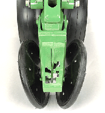 Rubber tire closing system
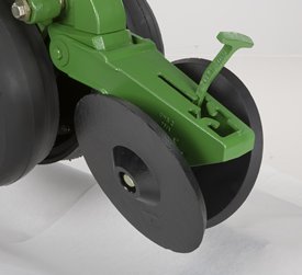 Cast wheel closing system
Rubber tire closing systems are used for most conventional, minimum-till, and no-till planting conditions. The spacing between the wheels is adjustable so the closing system can meet the needs of those who want to plant small seeds at shallow depths.
The wheels can also be staggered fore and aft to enhance residue flow. Four levels of spring force are available and are easily set with the integrated T-handle adjustment. A lower force spring can be obtained from parts, if a lower amount of force is required.
Additional closing wheel options include:
- Cast closing wheels, for tough to close conditions
- Disk closing, for shallow planting depths
- Drag closing, for crust-and-bake conditions
- Closing wheel frame less wheels, for growers desiring to use aftermarket closing wheels
1725 Planter - integral stack-folding
Convenient, stack-folding design combined with rigid or flexible frame
 1725 16Row30 Stack-Fold Planter
The 1725 Stack-Folding design provides narrow transport capability for these integral, large-frame planters without the need to empty hoppers. 1725 Stack-Folding Planters have both rigid-frame and flex-frame configurations.
The 12-row wide planters (36-, 38-, or 40-in. spacings) are equipped for rigid operation but can be modified in the field to provide frame flex. Productivity is improved with in-cab fold and go. Stack-folding frames utilize side-fold markers or can also be ordered without markers.
The 1725 Stack-Fold Integral Planter is available in the following models:
Transportability
Model |
| Transport height* | |
Transport width | |||
with markers | |||
8-row (36 in.) | 16 ft, 5 in. | 11 ft, 2 in. | |
8Row (38, 40 in.) | 17 ft, 5 in. | 11 ft, 2 in. | |
12Row (30 in.) | 20 ft, 3 in. | 11 ft, 8 in. | |
12Row (36 in.) | 19 ft, 6 in. | 13 ft, 3 in. | |
12Row (38, 40 in.) | 23 ft, 8 in. | 13 ft, 3 in. | |
16Row (30 in.) | 26 ft, 8 in. | 13 ft, 2 in. | |
*Height measured with 18.4R-46 rear tires on tractor | |||
SeedStar™2 monitoring system
Integrated innovation--that is what operators will appreciate with the SeedStar 2 monitoring system and GreenStar™ 2 (GS2) Display. An increasing number of acres combined with rising seed costs drive the need to easily understand planter functions and monitor performance. It is all about making every seed count and that is what SeedStar 2 delivers.
The SeedStar 2 monitoring system is a full-feature, color, seed population monitor used in conjunction with the GS family of displays (GS 2600 or 2630 Display or the entry-level GS2 1800 Display). Conveniently, SeedStar 2 planting functions are fully integrated with the full spectrum of AMS applications—guidance, coverage maps, and field documentation can be shown all on one GS 2600 or 2630 Display.
When a SeedStar 2 system is used on a planter, there is no need for a ComputerTrak™ monitor. All vital planting information is displayed in one central, easy-to-read location.
SeedStar 2 features
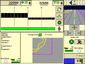
 SeedStar 2 full-screen planter run page
SeedStar 2 is a user-friendly system that has retained all the valued features of SeedStar and incorporated the next generation of enhancements. For example, on-screen, color indicators shows drive engagement/disengagement status. In addition, three color (black, orange, or red) planter at a glance bars visually inform the operator of row population status.
Not only does SeedStar 2 incorporate the use of color but it utilizes an intuitive icon and folder based operator interface. Icons are easy to understand across many languages and reduce the need for text. Icons for planter main run page, planter setup, seed/crop setup, totals, and diagnostics are located in the soft-key region of the display. Setup is performed by selecting the appropriate icon and then choosing the tabs to enter/select information.
The SeedStar 2 monitor offers all of the features and functionality of the ComputerTrak 350 monitor and much more. SeedStar 2 monitors the following planter functions:
- Row population/spacing
- Row failure
- Average population (entire planter and by variable-rate drive [VRD] motor section)
- Vacuum level
- Fertilizer pressure
- Acre counter
- Total acreage
- Tractor speed
In addition, planter operational information is available within the SeedStar 2 monitor system. Such operational information includes population charts, seed disk vacuum settings, and setting recommendations for the piston pump liquid fertilizer system.
All SeedStar 2 systems have the capability, through a single controller, to perform both the seed monitoring and variable rate drive functions. SeedStar 2 monitoring is required for VRD population control. Even though the planter may not be equipped with SeedStar 2 VRD, the SeedStar 2 monitoring system is available and will allow for future installation of VRD.
SeedStar 2 enhancements
 SeedStar 2 half-screen planter run page
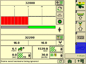 SeedStar 2 showing half-width disconnect status
The SeedStar 2 enhanced planter features include:
- GreenStar 2 display integration. Eliminates the need to operate the GS2 2600 Display in the original GreenStar monitor mode or the use of dual displays
- User-friendly, intuitive icons
- Half- or full-screen run page
- On-screen, color drive status; a quick glance at the display tells the operator if the half-width disconnect is engaged or disengaged
- Three-color planter-at-a-glance population bar. A black bar indicates that population is close to target and within established limits; orange shows the population is above/below the alarm set point; red signals the population is out of operating range or is not planting
- Three-piece, color VRD indicator. Each piece of the VRD gear pie turns green when the wheel motion sensor is active, planter is lowered, and drives are engaged
- ISO 11783. Communication standard between controllers and displays
SeedStar monitoring original features
SeedStar 2 retains all those SeedStar features that producers value and have come to expect:
- Planter at a glance. Allows operator to view relative population levels of all rows on one screen
- Automatic valve calibration. With the SeedStar VRD, this is now completed automatically. There is no longer a need to manually calibrate the hydraulic valves
- Increased population updates. SeedStar will now update population levels once a second at planter start up then approximately once every three seconds
- Mapping of actual seed rates. When combined with Field Doc™ system, actual and target seeding rates can now be mapped in Apex™ software
- Reprogrammable utilizing CAN via Service ADVISOR™ diagnostics system
- Improved diagnostics/event recorder. On SeedStar VRD planters, additional diagnostic information is available, as well as an event recorder to capture system performance data at a specific point in time
- Ability to run motors at different population levels. On SeedStar VRD, operators running multiple motor systems can run each motor at a different speed, allowing different population levels within a planter
- User-configurable high fertilizer pressure alarm. Allows the operator to be warned when fertilizer pressure reaches a specific level
- Automatic quick-start for SeedStar VRD. No longer does the operator need to press the quick-start button on end row turns to resume planting
- Automatic tractor speed source selection. When equipped with an 8000/9000 Series Tractor, the system selects the radar speed or allows for manual speed input selection
Seed variable-rate drive
Seed variable-rate drive provides the ultimate planting productivity by utilizing one, two, or three hydraulic motors (varies by model) to turn the seeding drive shaft. Hydraulic control of the seeding drive allows for on-the-go seeding rate changes right from the display mounted inside the tractor cab. Combine this seeding flexibility with the map-based planting option, and seeding rates adjust automatically based on the prescribed map.
Variable-rate drive offers the following advantages over common, ground, or contact-tire drive systems:
- Rate changes are almost instantaneous; no ramp up or ramp down of system as in some competitive systems
- Permits the producer to match seed population based on different soil types or irrigation practices
- John Deere design provides added operator safety by eliminating any possible drive creep found in some competitive variable-rate drive systems
 1755 equipped with variable-rate drive
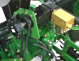 1765NT equipped with variable-rate drive
Single- or dual-motor systems for variable-rate drives are available for all John Deere planters except the 1785 Rigid Frame. Variable-rate drive is available as a factory-installed option for all applicable planter models.
Single- or dual-motor systems are available as field-installed attachments for most planter models; however, a three-motor variable-rate drive field-installed attachment is not available.
Seed variable-rate drive requires the SeedStar™ monitor and a radar input signal. Either tractor or planter radar may be used. Planter radar is ordered separately.
NOTE: Peanut seed meter disks require the Variable Drive Transmission.

We have a range of finance options to suit any customer. Contact your local Emmetts branch, or visit these sites for more information and a free quote.