- Available in 1.6 bu. or 3 bu. MaxEmerge™ 5 row unit
- Insecticide option for 1.6 bu.
- 4-, 6-, and 8-row configurations
Features
Advance with MaxEmerge™ 5 advantages
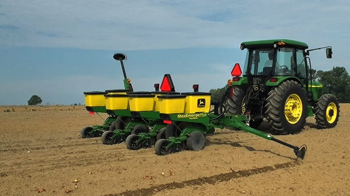
MaxEmerge 5 bundles the best of MaxEmerge XP and Pro-Series™ XP row-units to give you a unique planter solution. With more options and configurations, you’ll get difference-making versatility that easily adapts to your ag management plan.
It starts with optimal seed population that drives yield potential. An improved double eliminated helps achieve your desired population with a ride range of crop sizes. Improved side-hill performance of up to ¼ degree ensures you receive the full value of each seed when planting on terraces or rolling terrain. The vacuum air source from the Central Commodity System (CCS™) tank in the meter provides a debris-free environment for increased meter efficiency.
 MaxEmerge 5 with 56-L (1.6-bu) hopper plus insecticide
 MaxEmerge 5 with mini-hopper on CCS™ machines only
The MaxEmerge family of row-units have never seen a more versatile and efficient design until the MaxEmerge 5. The 5-family row-units improve productivity, increase uptime and lower the cost of ownership like never before.
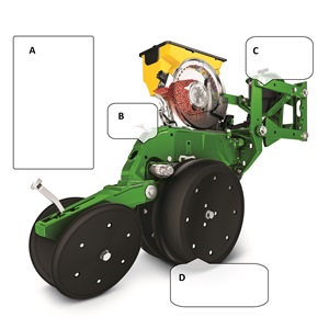
The MaxEmerge 5 row-unit was designed for improved performance and serviceability.
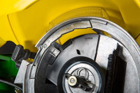
 Easily access the meter
Serviceability and changing crops have always been a focus of downtime and potential seed loss. The MaxEmerge 5 meter (shown on the right) is accessible without having to remove the box. The design allows large hoppers to be cleaned out the same as mini-hoppers, simply by opening the meter dome and catching the seed as it falls out.
 MaxEmerge 5 vacuum seed meter
The vacuum meter system gently pulls and holds individual seeds to the holes of the seed disk for population control and spacing accuracy, equaling better crop stands and profit. Vacuum seed meters can plant a wide variety of crops and seed types by simply changing seed disks and adjusting vacuum level. Vacuum seed meters are available for planters with MaxEmerge 5 row-units.
Additional features of the vacuum seed meter include:
- One moving component (the seed metering disk) for minimum maintenance requirements
- Meter located at each row-unit for accurate seed delivery
- Good hopper seed flow characteristics for longer operating time per hopper fill
- Low airflow in meter so seed treatments are not removed
 MaxEmerge 5 seed pool
The MaxEmerge 5 meter shape has also been redesigned for better seed flow. The mini-hopper design allows the planter to successfully operate on side hills up to 14 degrees.
Vacuum meter hub and latching handle
 MaxEmerge 5 vacuum meter with disk
Both the MaxEmerge 5 vacuum meters are equipped with a heavy-duty hub spring and disk latching handle. The spring ensures the seed disk stays properly positioned when operating flat-style seed disks and higher vacuum levels. Proper seed disk positioning means repeatable seed singulation, time after time. The disk-latching handle is designed for easy operation and effortless seed disk changeover. The hub is also machined to tight tolerances to further ensure alignment of metering components.
Operating characteristics of vacuum seed meter
 Operating speed with seed tube technology
The vacuum seed meter can operate at faster planting speeds than mechanical meters. However, planting accuracy will be influenced by seedbed conditions and the operating characteristics of the seed meter. Rough seedbeds and fast planting speeds (above 8.9 km/h [5.5 mph]) typically deteriorate seed placement accuracies when using seed tube technology.
The chart illustrates the effect operating speed has on population when using the vacuum meter. The operating band (color area) illustrates how the vacuum meter performs in relation to the desired population (indicated by horizontal line). The width of the band is due to various sizes and shapes of seeds and planting rate variations.
When operating on slopes above 15 degrees, increased or decreased population may result. To minimize this effect, reduce speed and consider using a flat style seed disk with increased vacuum level.
Vacuum meter seed disks
The ProMax 40 Flat Disk is a flat-disk planting solution field-proven to work since 1991.
 ProMax 40 Flat Disc
The design of the ProMax 40 Flat Disk position allows seed to be released from the optimum position above the seed tube. The flush-face seed tube allows the seed to drop uninterrupted through the tube.
The ProMax 40 Flat Disk utilizes flat holes and a higher vacuum level to ensure every hole is populated with a seed. A double eliminator gently removes multiple seeds at each hole for precise population control. A knockout wheel makes certain that each hole is clear of any debris after the seed is released from the disk.
 Flat-style and cell seed disks shown
The unique cell disk design allows planting a variety of seed sizes without any additional parts or individual meter adjustments. Another advantage of cell-type seed disks is the lower vacuum requirement compared to flat-style seed disks. Lower vacuum levels mean less hydraulic demand from the tractor. Most planting conditions call for a flat disk, if you are limited in hydraulic capacity, cell disks are recommended.
Double eliminator
 Flat seed disc and double eliminator
For difficult to singulate seeds, a flat seed disk and double eliminator is a viable alternative to traditional cell-type seed disks. By design, a flat seed disk requires higher levels of vacuum than a cell-type disk because there is no pocket or cell to hold the seed. The higher vacuum level will pull more than one seed to the holes in the seed disk. The double eliminator is set to cover a portion of the hole in the seed disk and is the mechanism to knock multiple seeds away as the disk rotates.
Double eliminators are required with flat-type seed disks only and should not be used with cell-type seed disks. The knockout wheel is also recommended in conjunction with the double eliminator and flat seed disk to ensure seed is ejected from the disk.
Flat and celled type seed metering disks are available to allow planting a wide variety of seed types.
- Corn (field, popcorn, or sweet corn)
- Soybeans
- Cotton
- Sorghum
- Sugar beets
- Sunflowers
- Edible beans/peas
- Peanuts
- Melons, squash, cucumbers
Mini-hopper row-units, which are used only with the CCS, are compatible only with crops that the CCS is approved to plant.
- Corn
- Popcorn
- Sweet corn
- Soybeans
- Sunflowers
- Sorghum
- Cotton
NOTE: Due to small seed size and low planting populations, sugar beets can be planted with mini-hopper style meters by adding hopper extensions and not using the CCS tank. These hopper extensions can also be used for planting test plots.
 Hopper shutoff
Also, to help with meter access of 56-L and 106-L (1.6-bu and 3-bu) hoppers the hopper shutoff feature was added. With the shutoff engaged, the meter cover can be opened without first having to remove all the seeds from the hopper. Lever down, the seed flow is on, lever horizontal and the seed flow is off.
 MaxEmerge 5 mini-hopper
There are significant changes to the MaxEmerge 5 mini-hopper. One update is the straight feed from the CCS hose to the mini-hopper to ensure a continuous free flow of seeds. This design change reduces the potential for plugging issues with larger seed size and the use of seed treatments. By drawing air from the CCS tank, the vacuum source is cleaner, preventing meter debris buildup.
 Ductile iron-cast shank
Ductile iron casting is a unique high-tech process that produces a single-piece row-unit shank this enables alignment from the seed trench to the closing wheel.
The row-unit head is also designed using the ductile iron-casting process. The row-unit head provides the mating joints between the row-unit parallel arms and the row-unit shank. It is also the upper attaching point for the seed meter and seed hopper.
Ductile iron casting of the row-unit shank and head assembly provides a row-unit that is 25 percent stronger than other competitive welded row-units.
 Tru-Vee opener blade
One of the trademark capabilities of John Deere planters has always been the ability of the Tru-Vee openers to provide an ideal seed furrow.
The thickness of the Tru-Vee opener blade is 3.5 mm (0.14 in.) this blade thickness will provide extended wear life.
The MaxEmerge 5 row-unit also provides better Tru-Vee opener bearings for longer life. The double-row ball bearing provides up to three times the wear life as the single-row bearing.
 Depth adjustment T-handle
John Deere planters provide consistent seed depth control in all field conditions. Depth control is a function of the Tru-Vee openers, the downforce system, and the gauge wheel assembly.
The gauge wheel itself is made of durable nylon composition with a concave profile. This profile gently firms the sides of the seed furrow, ensuring a well-defined trench. The shape reduces rocks and residue being picked up and thrown onto the drive chains and row-units and helps to prevent rooster tailing of soil.
The bolt-through design utilizes an open bearing in the gauge wheel that allows an attaching bolt to pass through the wheel to the threaded hole in the gauge wheel arm. This simple bolt-through design provides for a positive attachment of the gauge wheel to the gauge wheel arm and allows quick removal of the gauge wheel for service.
Adjustability of the row-unit is critical to good performance. More available downforce options than any row unit in the industry
- Adjustable heavy-duty downforce, four settings, 0 kg (0 lb), 57 kg (125 lb), 113 kg (250 lb), and 181 kg (400 lb) of downforce
- Pneumatic downforce, infinitely variable from 0 to 181 kg (0 to 400 lb) of downforce
- Active pneumatic downforce adjusts automatically for changing ground conditions from 0 to 181 kg (0 to 400 lb) of downforce
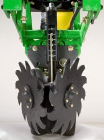
 Rubber tire closing system
 Cast wheel closing system
Rubber tire closing systems are used for most conventional, minimum-till, and no-till planting conditions. The spacing between the wheels is adjustable so the closing system can meet the needs of those who want to plant small seeds at shallow depths.
The wheels can also be staggered fore and aft to enhance residue flow. Four levels of spring force are available and are easily set with the integrated T-handle adjustment. A lower force spring can be obtained from parts, if a lower amount of force is required.
Additional closing wheel options include:
- Cast closing wheels for tough-to-close conditions
- Disk closing, for shallow planting depths
- Closing wheel frame less wheels for growers desiring to use aftermarket closing wheels
Downforce system options
Individual Row Hydraulic Downforce (IRHD)
 IRHD system
IRHD has been specifically designed to meet the needs of producers that are looking to adjust to the toughest field conditions and provide maximum yield potential from field to field, season after season. IRHD works as a closed-loop downforce system that reacts quickly on an individual row basis to changing soil conditions supporting increased ground contact, which can lead to improved seed depth consistency. When setting planter downforce margin, the system will apply the needed downforce by row to maintain ground contact.
The system allows operators to maintain gauge wheel ground contact leading to desired seed depth placement. IRHD can adjust five times per second and make adjustments of 45.4 kg (100 lb) in less than a second. The system has a total range of applied downforce from 22.7 kg (50 lb) to 204.1 kg (450 lb) and utilizes the power beyond circuit on the tractor. IRHD is 58 percent faster than the active pneumatic downforce solution. Fast reaction and increased ground contact can lead to improved emergence. With uniform emergence, some studies have shown a yield impact from 5 percent to 9 percent.
IRHD is controlled through the G5 Display with SeedStar 5. As shown below, operators can view ground contact or applied downforce using the toggle button.
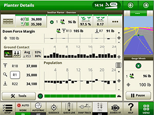 IRHD screen showing the ground contact graph
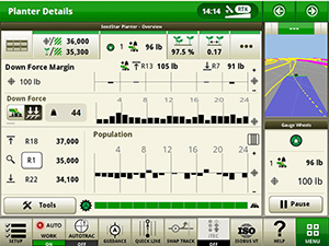 IRHD screen showing the applied downforce graph
IRHD accumulator
 IRHD accumulator
The IRHD actuator is the foundation of ensuring accurate seed depth and seed-to-soil contact at higher planting speeds up to 16.1 km/h (10 mph). The newly redesigned IRHD actuator was designed with durability and optimal performance in mind. Consisting of a valve, pressure sensor, cylinder, and now, two accumulators, the new design allows the operator to reduce downtime with recharges instead of replacements. With two rechargeable nitrogen accumulators built into the new IRHD actuator, it maintains performance, even at low nitrogen levels. This allows reduced downtime for the operator, and optimal performance over entire operating range. Pressure control from the IRHD actuator ensures optimal system performance by dampening shocks from field obstacles while operating in the field. The reduction of shock loads prevents excessive wear and broken row unit components due to the new robust and durable design. Frequently worn parts such as the accumulator pistons and seals can be replaced. The actuator rod has an internal retention feature to prevent oil loss in the event of a row unit failure.
Heavy-duty parallel arm for IRHD Planter row units available
 Downforce and margin example
- A - Margin – amount of additional downforce applied to a row-unit above and beyond what is required for penetration to achieve planting depth. This additional weight will ride on the depth gauge wheels.
- 54.4 kg (120 lb) + 36.3 kg (80 lb) = 90.7 kg (200 lb) – 68 kg (150 lb) = 22.7 kg (50 lb) of margin
- B - Weight of row-unit - 54.4 kg (120 lb)
- C - Downforce – force that is applied to the row-unit by the air bag circuit - 36.3 kg (80 lb)
- D - Resistance from soil - 68 kg (150 lb)
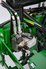
 Active downforce compressor assembly
A hydraulically driven compressor works with the G5 Display with SeedStar 5 systems to automate downforce control. Just set the row-unit target margin value and the active pneumatic downforce system works automatically. The system will make sure the planter maintains this value, achieving precise soil penetration, and consistent planting depth, without sidewall soil compaction. From the factory, the system is set at 45.4 kg (100 lb) target downforce margin but may be modified for varying field conditions. This frees the operator from constantly making manual downforce adjustments as conditions change.
This system offers a split-rank control feature for 1795 and DB Split-Row Planters. On split-row planters, active downforce will control the front and rear rows independently. This compensates for differing downforce requirements between the ranks that can be caused by things like different tillage or insecticide attachments and will help maintain an accurate planting depth and consistent margin across all the rows.
Active pneumatic downforce is available as factory installed or as an attachment for field conversion.
Set point row-unit downforce
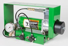
 Air compressor mounted on 1775NT outer hitch
On set point, the air compressor will be mounted on the outer hitch or frame assembly. Since the electric air compressor assembly is mounted on the outer hitch (as noted in the picture above) or frame, adjustments for row-unit downforce and related system pressures will be made electronically with the display.
When adjusting the amount of row-unit downforce using the display, the operator will select the amount of downforce (kg [lb]) to be applied across the planter. Depending on the soil conditions at hand, the operator might need to adjust the relative amount of row-unit downforce being applied during the planting operation. The integrated pneumatic downforce controls within the display will only allow for set-point operation and not automatic control as the planter is operating in different soil conditions. The pneumatic downforce system does not have the capability to automatically adjust downforce.
Pneumatic downforce provides convenient, simple adjustment of downforce for the whole planter from one location. The amount of downforce applied is infinitely adjustable from 6.8 to 181.4 kg (15 to 400 lb). Pneumatic downforce provides more consistent downforce throughout the range of row-unit travel than mechanical spring downforce systems.
Features include:
- 9.5-mm (3/8-in.) air delivery line instead of the 6.4-mm (1/4-in.) line used on model year 2010 and older planters.
- Air compressor assembly increased duty cycle. With this compressor, it provides a 47 percent increase in maximum air flow delivery compared to the prior air compressor.
- Pneumatic air bags with 9.5-mm (3/8-in.) air line inlets that have greater durability.
 Pneumatic downforce compressor and gauge
An improved compressor is used to charge the pneumatic system. This compressor can be located on the planter frame or in the tractor cab if desired. A gauge at the compressor indicates the amount of downforce being applied.
Integrated pneumatic downforce system
The functional features of the integrated system are the same as the standard pneumatic system, explained above, with the addition of control through the display.
Heavy-duty adjustable downforce springs
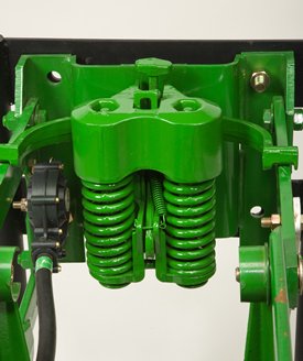 Heavy-duty adjustable downforce spring
Planter row-unit downforce is an important factor to ensure consistent and proper depth control. The heavy-duty adjustable downforce feature provides up to 181.4 kg (400 lb) of downforce. There are four settings available to allow the operator to choose the amount of downforce required for the condition: 0 kg (0 lb), 56.7 kg (125 lb), 113.4 kg (250 lb), and 181.4 kg (400 lb).
Row cleaner options to meet residue management needs
Crop yields have increased through the years along with the amount of residue left in the field after harvest. At the same time, tillage practices have changed, including different tillage operations which maintain large amounts of surface residue, and even no-till practices. Row cleaners are an essential tool in managing this increased amount of residue.
John Deere seeding group offers a variety of row cleaner options to meet the needs of a producer's operation. Compatibility varies by model, row spacing, and other planter equipment.
Screw-adjust, unit-mounted row cleaner
 Screw-adjust, unit-mounted row cleaner
The screw-adjust, unit-mounted row cleaner is mounted directly to the face plate of the row-unit, placing the ground engaging components just in front of the row-unit opener blades and depth gauge wheels. This close proximity allows the gauge wheels to control the depth of the row cleaner as well as the row-unit. This compact design also allows greater compatibility with fertilizer openers and other planter attachments.
SharkTooth® wheels are standard equipment on the unit-mounted row cleaner. The swept-tooth design of the wheel provides a clear path for the row-unit openers while resisting residue buildup on the wheel. The screw adjustment knob is accessible through the top of the parallel arms, providing convenient access for adjustments. The row cleaner can be adjusted in 1.6-mm (1/16-in.) increments, providing plenty of flexibility to meet the needs of changing conditions.
Floating row cleaner with unit-mounted coulter
 Floating row cleaner with unit-mounted coulter
The floating row cleaner allows a row cleaner to be used in conjunction with a unit-mounted coulter. This combination is often desired in heavy residue loads and reduced tillage planting conditions. The row cleaner provides a clear path for the row-unit, while the unit-mounted coulter helps penetrate tough soil conditions.
Accommodating the unit-mounted coulter means the residue wheels are farther forward from the row-unit face plate than in the case of the screw-adjust row cleaner. To maintain performance, this row cleaner has the capability to float above a defined minimum depth.
Standard depth-gauging bands on the wheels allow the row cleaner wheels to float independently of the row-unit openers, allowing both to perform in varying terrain. The unit may also be set in a fixed position by simply pinning through the bracket if desired. This row cleaner also features SharkTooth wheels as standard equipment.
The floating row cleaner and unit-mounted coulters are available on many planters as factory-installed equipment.
NOTE: Screw-adjust row cleaners are not compatible with MaxEmerge™ 5e row-units with long parallel arms.
NOTE: DB models have the option for either unit-mounted coulter, screw-adjust row cleaners, or pneumatic row cleaners (only compatible with MaxEmerge 5e or equipped ExactEmerge™ models). The DB60T is only available with a less row cleaner option.
SharkTooth is a trademark of Yetter Manufacturing, Inc.
Seed variable-rate drive
Seed variable-rate drive provides the ultimate planting productivity by utilizing one, two, or three hydraulic motors (varies by model) to turn the seeding drive shaft. Hydraulic control of the seeding drive allows for on-the-go seeding rate changes right from the display mounted inside the tractor cab. Combine this seeding flexibility with the map-based planting option, and seeding rates adjust automatically based on the prescribed map.
Variable-rate drive offers the following advantages over common, ground, or contact-tire drive systems:
- Rate changes are almost instantaneous; no ramp up or ramp down of system as in some competitive systems
- Permits the producer to match seed population based on different soil types or irrigation practices
- John Deere design provides added operator safety by eliminating any possible drive creep found in some competitive variable-rate drive systems
 1755 equipped with variable-rate drive
 1765NT equipped with variable-rate drive
Single- or dual-motor systems for variable-rate drives are available for all John Deere planters except the 1785 Rigid Frame. Variable-rate drive is available as a factory-installed option for all applicable planter models.
Single- or dual-motor systems are available as field-installed attachments for most planter models; however, a three-motor variable-rate drive field-installed attachment is not available.
Seed variable-rate drive requires the SeedStar™ monitor and a radar input signal. Either tractor or planter radar may be used. Planter radar is ordered separately.
NOTE: Peanut seed meter disks require the variable-drive transmission.
Seed variable-rate drive (VRD) with half- or three-width disconnect
 VRD shown on a 1775NT
The seed variable-rate drive provides the ultimate planting productivity by utilizing one, two or three hydraulic motors (varies by model) to turn the seeding drive shaft. Hydraulic control of the seeding drive allows for on-the-go seeding rate changes right from the display mounted inside the tractor cab.
Combine this seeding flexibility with the map-based planting option, and seeding rates adjust automatically based on a prescription map.
Single- or dual-motor systems for variable-rate drives are available for all John Deere planters except the 1785 Rigid Frame. Dual- or three-motor drive systems are commonly used on larger (12-row and more) planters and offer the capability of half-width or three-section drive disconnect.
The VRD is available as a factory-installed option for all applicable planter models. Single- or dual-motor systems are available as field-installed attachments for most planter models; however, a three-motor VRD field-installed attachment is not available.
The seed VRD requires the SeedStar™ monitor and a radar input signal. Either tractor or planter radar may be used. Planter radar is ordered separately.
VRD offers the following advantages over common, contact-tire drive systems:
- Almost instantaneous rate changes – there is no ramp up or ramp down of system as in some competitive systems
- Permits the operator to match seed population based on different soil types or irrigation practices
- John Deere design that provides added operator safety by eliminating any possible drive creep found in some competitive variable rate drive systems
Half-width drive disconnect
The half-width drive disconnect feature is excellent for the producer concerned with controlling seed costs. This feature helps the operator place seed in the desired area and limit the amount of costly overlapped planting.
The half-width drive disconnect allows the operator to turn off half of the planter at a time for planting end rows, point rows, etc. Variable-rate-equipped planters require two drive motors to utilize the half-width disconnect feature.
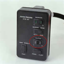 Half-width drive disconnect within frame control
With a 1765, 1765NT, and 1775 12-Row Planter, a single switch box is required for planters that are ordered with variable rate drive and half-width disconnect.
For the 1775NT, 1775NT Central Commodity System (CCS™), and 1795 Front-Folding Planters, the half-width drive disconnect switch is contained within the frame control box, conveniently located in the tractor cab. The function easily shuts off the drive for the left or right half of the planter row-unit seed meters.
Three-width drive disconnect
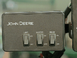 Three-width drive disconnect control
Three-width drive disconnect is an option on 1725 12-Row Planters and is base equipment on the 1725 16Row30 Planter. This feature is activated by three individual console mounted switches (control box), conveniently located in the tractor cab. The function easily shuts off the planter row-unit seed meters by one-, two-, or three-drive segments independently.
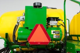
John Deere liquid fertilizer system delivers row-to-row accuracy
Block manifold delivery system
 Block manifold distribution
Delivering consistent and accurate fertilizer rates to each row is critical with any liquid fertilizer delivery system. The John Deere liquid fertilizer system utilizes 12-port block manifolds to equally distribute flow to the opener or in-furrow method of application. Liquid is distributed to each row through a 7.6-mm (0.3-in.) hose.
There are check valves at each row to ensure the system remains primed and flow stops immediately when planter is lifted. An orifice is located in-line and provides the restriction needed to achieve desired system pressure for excellent rate accuracy.
This delivery system will operate between 103.4 kPa and 620.5 kPa (15 psi and 90 psi), depending on the orifice size and rate. System pressure should not exceed 689.5 kPa (100 psi). Four orifice sizes allow operators to achieve a variety of rates all with optimal system performance and row to row accuracy. See rate chart below for model by model minimum and maximum application rates.
An 80-mesh washable screen is in place between the tank and the pump. It is essential to have this screen (AA40216) and associated fittings in place ahead of the fertilizer pump, even if not using a factory tank and quick-fill system. This screen is utilized to catch any blocks in the system caused by liquid fertilizer impurities. It is not recommended to use the 50-mesh screen.
 80-mesh screen and fittings
 Fertilizer rate chart located on planter
Refer to this chart or the operator’s manual for fertilizer rate settings.
Model | Minimum rate, | Maximum rate, |
755, 1765, 1775NT 12R, 1775NT 16R - 76 cm (30 in.) | 22.5 (2.4) | 351.7 (37.6) |
1755 - 91.4 cm (36 in.) | 18.7 (2.0) | 292.8 (31.3) |
1755 - 96.5 cm (38 in.) | 17.8 (1.9) | 277.8 (29.7) |
1775NT 24R Fixed-rate pump | 29.9 (3.2) | 290 (31.0) |
1795 | 30.9 (3.3) | 265.7 (28.4) |
DB44 24R22 | 37.4 (4.0) | 187.1 (20.0) |
DB60 24R30 | 28.1 (3.0) | 131 (14.0) |
DB60 47/48R15 | 46.8 (5.0) | 131 (14.0) |
DB60 36R20 | 37.4 (4.0) | 131 (14.0) |
DB66 36R22 | 37.4 (4.0) | 112.2 (12.0) |
DB80 48R20 | 37.4 (4.0) | 93.5 (10.0) |
DB88 48R22 | 37.4 (4.0) | 93.5 (10.0) |
DB90 36R30 | 28.1 (3.0) | 74.8 (8.0) |
DB80 32R30 | 28.1 (3.0) | 74.8 (8.0) |
DB120 48R30 | 28.1 (3.0) | 65.5 (7.0) |
NOTE: 1.02-mm (0.04-in.) yellow orifices and 1.8-mm (0.07-in.) black orifices are included with this system from the factory. For producers wanting to apply higher or lower application rates, two additional orifice sizes are available through Service Parts; 0.76-mm (0.03-in.) green (A91474) and 25.4-mm (1-in.) grey (A91478). Refer to rate charts in the operator’s manual or decal for details.
Fertilizer pump and opener options
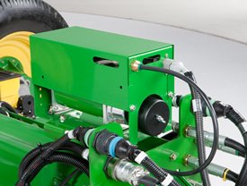
 Fixed-rate CDS-John Blue Company® piston pump
This liquid fertilizer delivery system is compatible with the fixed-rate pump. The system can be ordered with openers or with an in-furrow applicator.
The John Deere liquid fertilizer system utilizes ground-drive piston pumps for accurate delivery of liquid fertilizer to the manifold. These cast iron pumps contain stainless-steel components to reduce corrosion. Components subjected to abrasion are chrome-plated for increased wear. Strainers trap foreign material to reduce plugging. The positive displacement of the single piston, variable stroke pumps ensures consistent fertilizer delivery row-to-row from 7.6 L to 143.8 L (2 gal. to 38 gal.) per acre on planters with 76.2-cm (30-in.) spacing. Row-spacing configurations other than 76.2 cm (30 in.) have different pump capabilities.
Application rate of fertilizer is not dependent on ground speed and is not affected by viscosity of fertilizer solutions. The design of the piston pump makes for easy operation and adjustment. The chain-driven pump with a double sprocket assembly provides easy changeover from high to low fertilizer application rates. The application rate of the liquid fertilizer is set by referring to the rate decal and adjusting the pump setting.
CDS-John Blue is a trademark of Advanced Systems Technology, Inc.
Granular fertilizer systems
Granular fertilizer hopper and transmission
 Granular fertilizer hopper and opener
Granular fertilizer is available for 1755, 1775, and 1785 Planters. Fertilizer hoppers/tanks and selected other equipment may not be installed to facilitate shipping. Fertilizer attachments place fertilizer only on 76.2-cm, 91.4-cm, or 96.5-cm (30-in., 36-in., or 38-in.) spacings. Some planter frame and row spacing combinations result in the opener offset 10.1 cm to 15.2 cm (4 in. to 6 in.) from the centerline of the Tru-Vee opener.
Hoppers hold approximately 249.5 kg (550 lb) of fertilizer for longer operating time between fill-ups. One hopper feeds two rows. Hopper lids provide a large opening for fast filling with less spillage. Hoppers pivot for easy dumping and cleaning.
The transmission (two on 1775) has 24 sprocket combinations in consistent 6 percent increments to allow operators to apply fertilizer at the desired application rate. Depending on which auger is selected, a wide range of fertilizer rates can applied from 52.7 kg/ha (47 lb/acre) to 803.7 kg/ha (717 lb/acre). It requires openers or a surface application bracket.
Augers for granular fertilizer system
Low-, regular-, or high-rate feed augers are required to complete the granular fertilizer system. Augers move fertilizer from the fertilizer boxes to the opener. Regular- or high-rate augers are matched with the opener style selected and are available as a factory-installed option or as an attachment for field conversion. Low-rate augers are only available as an attachment for field conversion.
For 76.2-cm (30-in.) rows, the approximate rate of application is as follows:
- Low-rate augers – 52.7-139 kg/ha (47-124 lb/acre)
- Regular-rate augers – 105.4-533.5 kg/ha (94-476 lb/acre)
- High-rate augers – 183.8-803.7 kg/ha (164-717 lb/acre)
For 96.5-cm (38-in.) rows, the approximate rate of application is as follows:
- Low-rate augers – 41.5-208.5 kg/ha (37-186 lb/acre)
- Regular-rate augers – 82.9-418.1 kg/ha (74-373 lb/acre)
- High-rate augers – 124.4-626.6 kg/ha (111-559 lb/acre)
NOTE: Weight metered may vary from that indicated because the fertilizer attachment will meter by volume not by weight and because of differences in fertilizer density.
1755 and 1785 granular fertilizer openers
 Granular fertilizer opener
Frame-mounted, double-disk openers and frame-mounted, single-disk openers for granular fertilizer are available on the 1755 and 1785 Planters. The frame-mounted, single-disk opener is available with a regular spout or cast spout. Fertilizer openers place the granular fertilizer into the soil for maximum plant uptake and are adjustable. Single-disk fertilizer openers are required for no-till, but are also suitable for conventional and reduced tillage. Double-disk fertilizer openers should only be used in conventional and reduced tillage conditions.
- Single- and double-disk openers are compatible with frame-mounted coulters.
- Single-disk opener with cast spout is recommended for all soil conditions because it keeps soil from flowing into the furrow before fertilizer is delivered.
- The gauge wheel on single-disk openers will help gauge fertilizer application depth and minimize soil disruption.
- On 1755 8Row30 Planters, due to frame limitations, the granular fertilizer systems with single-disk openers can place fertilizer no closer than 12.7 cm to 15.2 cm (5 in. to 6 in.) to the seed furrow on rows 4 and 5.
1770 granular fertilizer openers
Frame-mounted, single-disk fertilizer openers with cast spout are utilized on the 1775 12Row30 Planter. These openers are ideal for both conventional and no-till. The openers are adjustable to place the fertilizer in the soil next to the seed furrow for ideal nutrient placement and maximum plant uptake. A single gauge wheel allows the opener to follow the contour of the ground for ideal fertilizer depth placement. Single-disk fertilizer openers are compatible with frame-mounted coulters.
Variety of markers available to match planting needs
 Tri-fold marker shown
John Deere planters are equipped with a variety of marker designs, including non-folding, folding, fold-over, side-fold, and tri-fold markers.
Automatic or independent hydraulic alternation controls are available.
NOTE: Automatic alternation controls are not available on 1775NT 24-Row Planters.
Automatic control is connected to the planter lift system and provides automatic alternation when the planter is raised. This configuration is base equipment on the 1745 and1755 Planters.
Independent control is not connected to the planter lift system and provides automatic alternation of markers when a selective control valve (SCV) lever is activated. Independent markers require a separate tractor SCV. Independent markers are standard equipment on 1765, 1775NT, and 1795 Planters. Independent markers are optional on 1705, 1745 and 1755 Planters.
Less marker option
The 1705, 1745, 1755, 1765, 1775NT, and 1795 Planters (only 1795 models equipped with the 2-point hitch) can be ordered less markers. The less marker code is ideal for planting on beds or for producers who are comfortable utilizing tractor guidance systems for next pass alignment.
Hydraulic alternation provides the following capabilities depending on the type of marker control used:
Marker capabilities | Marker control | |
| Automatic | Independent |
Automatic alternation as planter is lifted | X | — |
Planting with both markers down (i.e., opening from center of field) | X | X |
Partially raising marker and returning same marker (i.e., crossing waterway) | X | X |
Raising marker only and returning same marker (i.e., planting around pole in field) | — | X |
Raising planter and marker and returning same marker (i.e., planting around pole in field) | X | X |
Marker breakaway protection
 Breakaway protection
Tension bolt breakaway protection assembly (A) securely anchors the marker to the frame. This system is designed to protect the marker from damage by breaking the bolt in the event it hits an obstruction. A self-contained tool for adjusting the assembly and capturing the retaining nut is standard.
Compatible with: 1705, 1745, 1755, 1765, 1775NT, 1795, and DB60
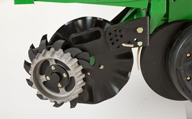
Marker disk blades
 406.4-mm (16-in.) notched marker disk
The 406.4-mm (16-in.) notched disk blade with 101.6-mm (4-in.) wide depth gauging band marks in all conditions; tough ground and high residue are no problem. The 101.6-mm (4-in.) wide depth band provides support in conventional-tilled ground so the blade is not too aggressive.

We have a range of finance options to suit any customer. Contact your local Emmetts branch, or visit these sites for more information and a free quote.