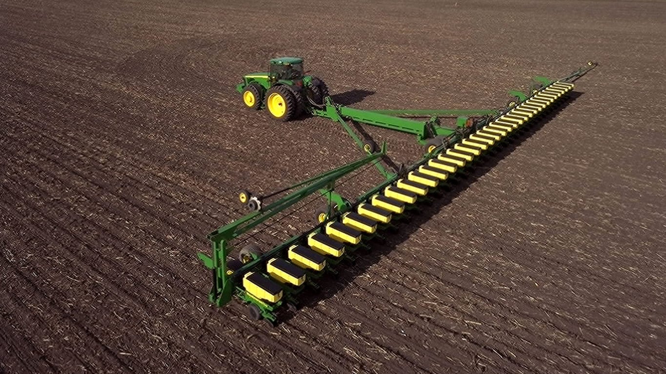
- 54-row planting width on 27.43 m (90 ft.) toolbar
- Row spacing options: 508 mm (20 in.), 559 mm (22 in.), 762 mm (30 in.)
- Equipped with MaxEmerge™ 5 twin row-units
- 3- and 5-section frames
Features
Increase visibility with planter auxiliary camera
 Planter auxiliary camera
 The planter auxiliary camera utilizes an adjustable magnetic mounting base. This allows customers the ability to move and adjust the field of view to see what’s most important to them.
- Camera is integrated into the SeedStar™ 5 planter Ethernet system, video is streamed to the CommandCenter™ display
- Camera is mounted to an adjustable magnetic base allowing customers full adjustability of their field of view
- Configurable with existing programmable video triggers
- Compatible with model year 2025 and newer SeedStar 5 planters and performance upgrade kits
- Mirror image view and adjust field of view from the video app on the G5 CommandCenter™ display
 Adjustable magnetic camera mounting bracket
Improve liquid fertilizer tendering logistics with fertilizer level sensors
 Picture of the liquid fertilizer level sensor
Liquid fertilizer level sensing is available on model year 2026 electric drive planters.
Fertilizer level sensing allows farmers to know how much liquid fertilizer is left in the tank from the convenience of the cab. The fertilizer level is displayed on the G5 CommandCenter™ Display in the SeedStar™ app.
- Better coordinate fertilizer tendering plans by knowing how many total gallons of liquid fertilizer are left on the planter.
- See total gallons of liquid fertilizer left on both planter and tractor if tractor is equipped with ExactRate™ tractor tanks.
- Enables customizable low fertilizer tank level warning alarms to prevent running out of liquid fertilizer.
- Fertilizer tender drivers and farm managers can remotely view fertilizer tank levels from a smart connected device using the John Deere Operations Center™ mobile app.
- Removes the need for the operator to manually set the fertilizer tank volume and enter the specific gravity.
 View cumulative fertilizer tank levels on both 8RX ExactRate tanks and planter liquid fertilizer tank levels on the G5 CommandCenter Display
Improve seed tendering logistics with CCS™ tank level sensors
 CCS tank levels displayed in the SeedStar™ application
Seed level sensing is available on all model year 2026 electric drive planters equipped with Central Commodity System (CCS) tanks operating on the SeedStar™ 5 planter application.
Seed level sensing gives farmers better knowledge of planter seed levels. This reduces the risk of running out of seed while planting also allowing farmers to better manage seed tendering logistics to have the seed in the right place at the right time.
View individual and total tank levels from the G5 CommandCenter™ display in the SeedStar app:
- Better plan tendering logistics with seed volume or seed percentage remaining
- Remotely view seed tank percent levels from your computer using John Deere Operations Center™ or from your connected smart device using the John Deere Operations Center mobile app
- Individual tank level displayed helps farmers prevent one tank emptying before the other
- Enables customizable low seed tank level warning alarms
 Customizable tank level alarms - view tank 1, tank 2 and total seed volume on G5 Display
Frame weight distribution
 1775NT 24Row with frame weight distribution
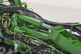 Hydraulic cylinder mounted on planter wings for frame weight distribution
As planters get larger and more customizable, there is more weight being carried by the center mainframe. This presents the possibility that weight may not be distributed evenly along the width of the planter frame during planting in certain circumstances. Some studies have shown there could be a potential yield loss of 70.5 L (2 bu) per acre in certain soil conditions from unequal weight distribution with more weight being on the center of the planter. The option has been added to have hydraulic cylinders mounted onto the frame of the planter that redistribute weight from the center of the planter to the rest of the tool bar.
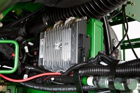
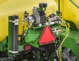 Accumulator is mounted near the air compressor to absorb any spikes of pressure
The frame weight distribution can be enabled or disabled on the G5 CommandCenter™ or Universal Display with SeedStar™ 5 on MaxEmerge™ 5e or ExactEmerge™ equipped planters. On model year 2025 planters and newer, SeedStar™ 5 provides the capability to adjust frame weight distribution from the cab.
 SeedStar™ 5 in-cab adjust
The system utilizes the tractor’s power beyond feature with load sense. Frame weight distribution is activated by the height switch, providing equal weight distribution at all times. In the scenario where a planter is equipped with frame weight distribution and onboard power generation for electric drives, there will be an orifice that directs hydraulic flow to fulfill the power generation requirement first and then provide oil to frame weight distribution.
On Model Year 2025 planters and newer, frame weight distribution can be adjusted from the cab on the G5 display. The system does not have active adjustment capabilities. When the planter is raised on headland turns, the system maintains pressure to the outside wings for a period of time to keep the system engaged to make the turn and reduce center frame tire weight on headlands.
In-cab adjust available on the following models with ExactEmerge or MaxEmerge 5e row units: all 1775NTs, 1795 24R20, 1795 31R15, 1795 32R15, DB44 24R22, all DB60s, DB66 36Row22, and DB90 54Row20. Frame weight distribution on models with MaxEmerge 5 will need to be manually adjusted from the valve block under the CCS tank.
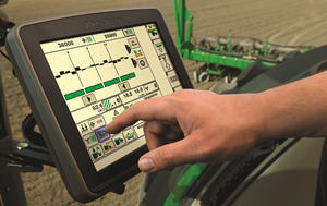
SeedStar 5 enables new planting technology
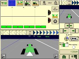
 SeedStar 5 screen example
Overview
SeedStar 5 is the latest monitoring software for John Deere planters available for Model Year 2025. This system is paired with G5 displays and Implement Ethernet to provide high-definition documentation, faster data speeds, and more information in the cab.
Benefits
- Faster data speeds
- High Definition (5Hz data) documentation
- Enables new technology like ExactShot and FurrowVision
- Building block for future planter automation
Additional details
Requirement:
- G5 Display
- Planter Implement Ethernet (included on model year 2025 planters)
- Building block for future planter information
Increase productivity with ExactEmerge™ trench delivery system and BrushBelt™ delivery system
It is very challenging to get the crop planted during the optimum planting window or as close to the optimum planting day as possible. Rate-of-yield loss accelerates greatly after the optimum window has passed. This is especially true in the northern U.S. and Canada. ExactEmerge maintains accurate speed placement at higher speeds; growers can avoid missing that peak planting time, thereby helping to get the highest crop yields.
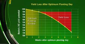 Yield loss after optimum planting day
With the BrushBelt trench delivery system, the spacing in the trench does not change from even to uneven terrain. This can be a problem with a traditional seed tube. Seed bounce and ricochet may occur as slopes increases, ultimately decreasing seed spacing performance.
The design of the BrushBelt system provides the best solution for the lowest release of seed to the bottom of the trench. The use of a brush provides the meter with an infinite amount of placement opportunities for each seed. This is what gives producers the confidence that every seed will have the desired spacing that a seed tube cannot provide.
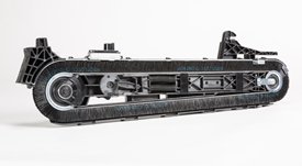 Maintenance-free BrushBelt system
When the brush comes around the pulley, it expands and allows the seed to be transferred from the bowl to the brush very easily. The brush then carries the seed down toward the trench, ensuring that there is no movement as it moves down the length of the cartridge.
Once the brush reaches the lower pulley, the BrushBelt system expands again to loosen the grip on the seed, and the centrifugal force releases the seed. Another advantage with the BrushBelt system and cartridge at all speeds up to 16.1 km/p (10 mph) is the ability to match the seed rearward trajectory to the forward ground speed of the planter. This provides a dead drop of the seed with no bounce and no roll at the bottom of the trench.
 BrushBelt conditioner engages brush bristles
John Deere’s ExactEmerge cartridge is self-cleaning. When an operator uses seed treatments or is forced to plant in less than ideal soil conditions, the design of the trench delivery system sheds buildup from the BrushBelt. A brush conditioner is located at the bottom of the cartridge to remove remaining residue and prevent the bristles from sticking together.
 Brush proximity helps clean sensor
Another advantage over a seed tube is that the BrushBelt system also acts as a cleaner to the seed sensor compared to a seed tube.
 Sensors for trench delivery system
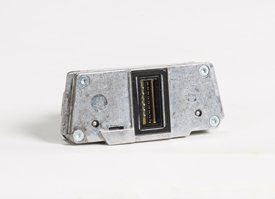 Reflective seed sensor
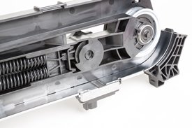 Sensor on trench delivery system
On all ExactEmerge row-units, each cartridge is equipped with sensors. As the seeds are being delivered through the BrushBelt delivery system controls, they pass the reflective seed sensor. The delivery system slides every seed past the seed sensor to read and send the signal to the controller. The seed sensor and design can provide sensor performance at higher seeds per second with no population adjustment as needed with seed tube sensors. This seed sensor data is actual row-unit performance data. In comparison, seed tube sensors add 10 percent population in soybean planting to adjust for the seeds missed due to placement within the seed tube. The BrushBelt system holds each seed in place until released in the trench, allowing the seed sensor a more accurate read.
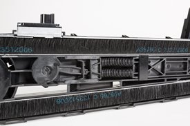
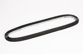 BrushBelt removed from trench delivery system
The BrushBelt system requires no maintenance and has a wear life designed to match the wear life of the other wear components. Since operations vary, as do soils and field content, it is recommended to replace the BrushBelt after noticeable wear or decreased performance.
Changing the belt is easy. One latch removes the meter over the trench delivery system. Grab the cartridge by the grip and pull toward the body, releasing it from the electric motor fitting. Lift the trench delivery system up and remove the sensor wiring harness to completely pull the cartridge out of the row-unit.
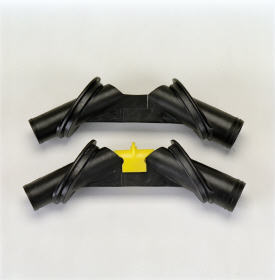
There are two plastic covers that snap off to uncover the belt; remove the covers and then twist the circular spring tensioner dial with the yellow arrow on it to release the tension on the springs. Once tension has been removed, pull the belt out. It is also recommended to change the stainless-steel wear strip at this time as well, which also slides right out of place without the use of tools.
NOTE: It is recommended to use a talc/graphite mixture with ExactEmerge. Best results have been 80 percent talc and 20 percent graphite. For certain regions and territories, talc and talc/graphite mixes are restricted from use; in this case, use a wax-based fluency agent.
SeedStar™ XP monitoring system
SeedStar XP overview
 SeedStar XP shown on the GreenStar™ 3 2630 Display
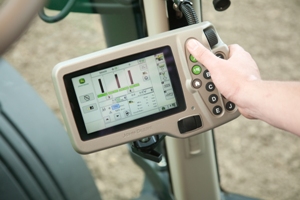 SeedStar XP shown on the GreenStar 2 1800 Display
Building upon the foundation of SeedStar 2, the SeedStar XP system takes planter monitoring to the next level. Specific information about how the planter is performing enables the operator to make needed adjustments for implement optimization.
SeedStar XP is compatible with:
- GreenStar 2 1800 Display
- GreenStar 2600 Display
- GreenStar 3 2630 Display
- Gen 4 4200 CommandCenter™ Display
- Gen 4 4600 CommandCenter Display
- 4240 Universal Display
- 4640 Universal Display
- G5 Integrated and Universal Display
- G5Plus Integrated and Universal Display
- G5e (Ground Drive only)
SeedStar XP is not compatible with the Gen 4 Extended Monitor or G5 Extended Display.
The SeedStar XP planting functions are fully integrated with the full spectrum of Precision Ag Technology applications such as Swath Control Pro™ system for planters, Section Control, GreenStar AutoTrac™ assisted steering system, John Deere Operations Center, Documentation, and others. Integrated planting technologies for better asset utilization and ease of use is just part of what SeedStar XP provides.
SeedStar XP seed singulation monitoring
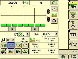 SeedStar XP seed singulation planter run page
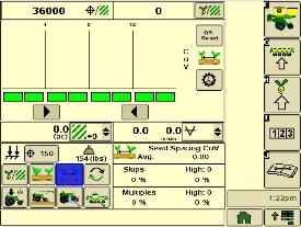
Understanding the meter singulation performance on the planter is critical to minimizing the amount of seed multiples and skips. As a result, the SeedStar XP monitoring system provides real-time information from the row-units about the overall seed singulation performance.
As seen in the screen shot image above, seed multiple information is displayed on the top portion of the planter-at-a-glance bar with seed skip information on the lower portion. This provides the operator a better understanding of relative seed multiple and skip data on a row-unit basis, all within one easy glance.
Also, within the seed singulation planter run page, information about row-units with the highest percentage of seed multiples and skips is provided in order to make necessary adjustments for better planter optimization.
SeedStar XP row-unit ride dynamics planter run page
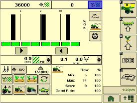 SeedStar XP ride dynamics planter run page
While operating a planter, travel speed and field conditions can affect the amount of row-unit bounce that is experienced. Excessive row-unit bounce or vertical motion can cause problems with meter performance. To better understand the amount of row-unit vertical motion when travelling through a field, the SeedStar XP monitoring system provides real-time information on row-unit ride dynamics.
As seen in the ride dynamics planter-at-a-glance screen shot image above, the SeedStar XP system provides ride dynamic information for each sensor node that is mounted on the planter. Each sensor node transmits ride dynamic information for each planter frame section to allow for the operator to make necessary operating adjustments to improve overall planting performance.
SeedStar XP row-unit downforce planter run page
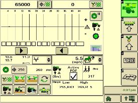 SeedStar XP downforce planter run page
As row-unit downforce systems gradually change from heavy-duty downforce springs to pneumatic downforce, being able to understand the amount of as-applied row-unit downforce is needed while operating the planter.
With various soil conditions, moisture, etc. experienced while planting, it is imperative to have the ability to change actual row-unit downforce to have enough force for the Tru-Vee openers to penetrate the soil media. However, in some conditions, having too much downforce applied to the row-units for effective opener penetration could cause problems with side wall compaction from the gauge wheel.
Side wall compaction within the seed furrow can cause hatchet roots to develop, or roots that do not have the ability to penetrate the seed furrow soil media. This could lead to poor plant emergence and eventually lower overall yield performance.
With the SeedStar XP monitoring system, row-unit downforce information is measured by the downforce sensor and sensor nodes and transmitted to display in the tractor cab (as seen in the image above). The row-unit downforce information is displayed on the top portion of the planter-at-a-glance bar with more row-unit downforce information on the lower portion.
Two different control options are available on 1775NT, 1795, and DB Series Planters for pneumatic downforce. The base pneumatic downforce system requires manual control of the downforce to maintain the desired planting results or row-unit margin. Optional active pneumatic downforce takes SeedStar XP even further by removing constant downforce adjustments from the operator and actively controlling the downforce system to maintain a desired target margin.
The 1745 Planter with pneumatic downforce and SeedStar XP will require manual control of the downforce to maintain row-unit margin.
SeedStar XP seed spacing monitoring
 SeedStar XP seed spacing planter run page
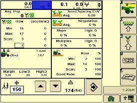
Throughout the planting process, obtaining good seed spacing is critical toward achieving plant growing conditions for maximum yield potential.
Today, many items are adjusted on the planter prior to planting to optimize overall seed spacing performance. After such adjustments are made, information about the actual seed spacing performance during planting was missing within the planter monitoring system. With SeedStar XP, seed spacing information is transmitted live via the GreenStar display to show the operator exactly what is happening with the planter behind them.
The SeedStar XP transmits seed spacing information onto the planter-at-a-glance bar for easy understanding of planter seed spacing performance. Also, information about seed skips and multiples is provided to help understand actual planter meter performance and other related system functions in order to make necessary adjustments if needed.
NOTE: Seed spacing and seed singulation information is only available when planting crops with seed drop rates below 40 seeds per second such as corn. With higher population crops such as soybeans the system does not provide spacing and singulation information because the number of seeds dropping per second is much higher.
SeedStar XP full planter performance page
 SeedStar XP planter details
 With the capability of monitoring differences in planting performance items such as seed singulation and row-unit downforce, having one screen to view all planter performance elements is needed to understand the whole planting system. SeedStar XP combines all of the various planting performance elements into one full-color, planter overview screen to enable for a quick understanding of relative planting functionality.
SeedStar XP half screens and other features
 SeedStar XP seed singulation half screen
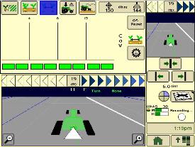 SeedStar XP seed spacing half screen
Other SeedStar XP monitoring features include:
- Capable of monitoring individual row-unit and overall planter performance in terms of seed spacing, singulation, and row-unit downforce
- Split-screen applications to enable use of popular guidance features such as AutoTrac assisted steering system
- On-screen indication of sensor node/downforce sensor assemblies once configured within the monitor settings application
- Full-color display icons for easy recognition and overall aesthetics
- Pneumatic downforce system controls with the GreenStar display application
SeedStar 2 monitoring original features
SeedStar XP retains all of those SeedStar 2 features that producers value and have come to expect:
- Planter-at-a-glance – allows operator to view relative population levels of all rows on one screen.
- Automatic valve calibration – with the SeedStar variable-rate drive (VRD), this is completed automatically. There is no longer a need to manually calibrate the hydraulic valves.
- Increased population updates – SeedStar will update population levels once per second at planter start up then approximately once every three seconds.
- Mapping of actual seed rates – when combined with documentation, actual and target seeding rates can be mapped in John Deere Operations Center.
- Reprogrammable utilizing controller area network (CAN) via Service ADVISOR™ diagnostics system.
- Improved diagnostics/event recorder – on SeedStar VRD planters, additional diagnostic information is available, as well as an event recorder to capture system performance data at a specific point in time.
- Ability to run motors at different population levels – on SeedStar VRD, operators running multiple motor systems can run each motor at a different speed, allowing different population levels within a planter.
- User-configurable high fertilizer pressure alarm – allows the operator to be warned when fertilizer pressure reaches a specific level.
- Automatic quick-start for SeedStar VRD – no longer does the operator need to press the quick-start button on end row turns to resume planting.
- Automatic tractor speed source selection – when equipped with an 8000/9000 Series Tractor, the system selects the radar speed or allows for manual speed input selection.
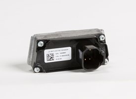
Components and operation
 Planter main 2 controller
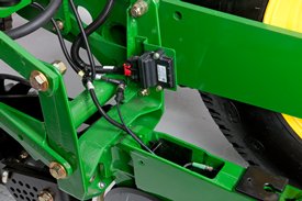 Sensor node assembly installed
The SeedStar XP monitoring system contains the following components in order to support the planting data transfer to the GreenStar 2 Displays:
- Seed monitor/variable-rate (SMVR) controller with model year 2011 or newer software
- Planter main 2 controller (installed on all SeedStar XP eligible models for model year 2011 or newer)
- Sensor node(s)
- Downforce sensor assembly
The planter main 2 controller processes the row-unit data from the sensor node assemblies located on the row-unit head casting. The processed information is then sent to the SMVR controller to be integrated into the displayed information being sent to the GreenStar Display.
Downforce sensor assemblies are found on row-units with sensor nodes installed. The downforce sensor assembly is assembled with the gauge wheel depth-adjustment handle and provides gauge wheel pressure information to the respective sensor node for data processing.
 Downforce sensor installed
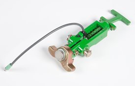 Downforce sensor assembly
Depending on the planter size, different configurations of sensor nodes and downforce sensors are installed in support of the SeedStar XP monitoring system.
DB fertilizer options
Option code 2625 – Liquid fertilizer with row-unit mounted in-furrow applicator:
- This option contains a ground driven pump, plumbing to a manifold, and routing to each row-unit. The in-furrow applicator places fertilizer after the seed and before the closing wheels.
The DB60 24Row Split 47 Planter and DB60 24Row Split 48 Planter applies fertilizer on 76.2-cm (30-in.) row spacing only.
Drawbar hitch
 Drawbar hitch
A factory-installed, optional drawbar hitch is available for use with 1775NT 16- and 24-Row, 1775NT Central Commodity System (CCS™) 16- and 24-Row, and 12.2-m (40-ft) 1795 Planters. For all DB models the drawbar hitch is in base. All DB models are available with Category 5 drawbar hitch. The following DB models are not available with Category 4 drawbar hitch: DB80 48R20, DB88 48R22, DB90 36R30, DB90 54R20, and DB120 48R30.
The planter drawbar hitch provides easy operation with plenty of ground clearance. The hitch design utilizes a hydraulic cylinder to raise the planter hitch for transport. Hydraulic oil for the hitch cylinder on 1775NT and 1795 Planters comes from the row marker system. Activation of this cylinder is accomplished using a single switch on the display and the marker selective control valve (SCV).
Due to the hydraulic system design, the drawbar hitch requires the planter be equipped with independent markers (not tied to planter lift circuit). Removal of markers from all planters, except the 1775NT 24Row30, makes the drawbar hitch inoperable. The 1775NT 24Row30 is the only planter where the drawbar hitch, less markers, is a valid combination.
For planting on 38.1-cm (15-in.) row spacing with a 16/32-Row 1795 Planter, the drawbar needs to be offset 19-cm (7.5-in.) on the tractor to center the planting rows behind the tractor. When the 16/32 1795 has a drawbar hitch, operators may not be able to offset the hitch to the exact specifications of 19-cm (7.5-in.) when planting in 38.1-cm (15-in.) operation, and could be off as much as a 1.3-cm (0.5-in.). To compensate, additional adjustments to the marker will be necessary.
When using a guidance system such as parallel tracking or AutoTrac™ assisted steering system, operators will need to use their implement offset when planting with all rows on 1795 Planters equipped with the drawbar hitch to compensate for the offset.
The drawbar hitch is ideal for those who have 9000 Series Tractors without a 3-point hitch. For these, the planter drawbar hitch is the economical choice instead of adding a 3-point hitch.
To accept the planter drawbar hitch, the tractor drawbar must be ordered with, or upgraded to, a Category 4 drawbar with the heavy-duty package or Category 5 to be compatible. Track tractors with wide-swinging drawbars are not compatible with the planter drawbar hitch due to a lower hitch-load capacity.
Each 1795 or 1775NT Planter ordered with the drawbar hitch will be shipped with a Category 4 hitch link installed. A Category 5 hitch link is also shipped with the planter if the planter is to be used with a Category 5 drawbar. See pre-delivery instructions included with the planter for changeover information.
Compatibility:
- Category 5 implement hitch links are not compatible with Category 4 tractor drawbars.
- Category 5 tractor drawbars are not compatible with Category 4 implement hitch links.
This hitch also adds 0.6-m (2-ft) to planter length during transport and field operation. There are some combinations of planter options that are not compatible with the drawbar hitch option due to tractor drawbar limitations.
Downforce system options
Individual Row Hydraulic Downforce (IRHD)
 IRHD system
IRHD has been specifically designed to meet the needs of producers that are looking to adjust to the toughest field conditions and provide maximum yield potential from field to field, season after season. IRHD works as a closed-loop downforce system that reacts quickly on an individual row basis to changing soil conditions supporting increased ground contact, which can lead to improved seed depth consistency. When setting planter downforce margin, the system will apply the needed downforce by row to maintain ground contact.
The system allows operators to maintain gauge wheel ground contact leading to desired seed depth placement. IRHD can adjust five times per second and make adjustments of 45.4 kg (100 lb) in less than a second. The system has a total range of applied downforce from 22.7 kg (50 lb) to 204.1 kg (450 lb) and utilizes the power beyond circuit on the tractor. IRHD is 58 percent faster than the active pneumatic downforce solution. Fast reaction and increased ground contact can lead to improved emergence. With uniform emergence, some studies have shown a yield impact from 5 percent to 9 percent.
IRHD is controlled through the G5 Display with SeedStar 5. As shown below, operators can view ground contact or applied downforce using the toggle button.
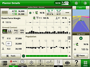 IRHD screen showing the ground contact graph
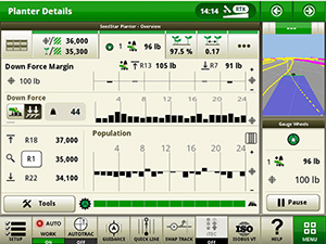 IRHD screen showing the applied downforce graph
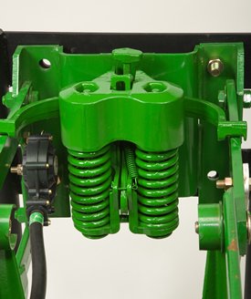
IRHD accumulator
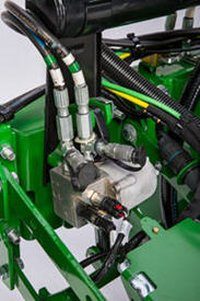
 IRHD accumulator
The IRHD actuator is the foundation of ensuring accurate seed depth and seed-to-soil contact at higher planting speeds up to 16.1 km/h (10 mph). The newly redesigned IRHD actuator was designed with durability and optimal performance in mind. Consisting of a valve, pressure sensor, cylinder, and now, two accumulators, the new design allows the operator to reduce downtime with recharges instead of replacements. With two rechargeable nitrogen accumulators built into the new IRHD actuator, it maintains performance, even at low nitrogen levels. This allows reduced downtime for the operator, and optimal performance over entire operating range. Pressure control from the IRHD actuator ensures optimal system performance by dampening shocks from field obstacles while operating in the field. The reduction of shock loads prevents excessive wear and broken row unit components due to the new robust and durable design. Frequently worn parts such as the accumulator pistons and seals can be replaced. The actuator rod has an internal retention feature to prevent oil loss in the event of a row unit failure.
Heavy-duty parallel arm for IRHD Planter row units available
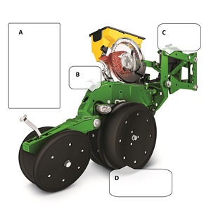 Downforce and margin example
- A - Margin – amount of additional downforce applied to a row-unit above and beyond what is required for penetration to achieve planting depth. This additional weight will ride on the depth gauge wheels.
- 54.4 kg (120 lb) + 36.3 kg (80 lb) = 90.7 kg (200 lb) – 68 kg (150 lb) = 22.7 kg (50 lb) of margin
- B - Weight of row-unit - 54.4 kg (120 lb)
- C - Downforce – force that is applied to the row-unit by the air bag circuit - 36.3 kg (80 lb)
- D - Resistance from soil - 68 kg (150 lb)
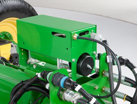
 Active downforce compressor assembly
A hydraulically driven compressor works with the G5 Display with SeedStar 5 systems to automate downforce control. Just set the row-unit target margin value and the active pneumatic downforce system works automatically. The system will make sure the planter maintains this value, achieving precise soil penetration, and consistent planting depth, without sidewall soil compaction. From the factory, the system is set at 45.4 kg (100 lb) target downforce margin but may be modified for varying field conditions. This frees the operator from constantly making manual downforce adjustments as conditions change.
This system offers a split-rank control feature for 1795 and DB Split-Row Planters. On split-row planters, active downforce will control the front and rear rows independently. This compensates for differing downforce requirements between the ranks that can be caused by things like different tillage or insecticide attachments and will help maintain an accurate planting depth and consistent margin across all the rows.
Active pneumatic downforce is available as factory installed or as an attachment for field conversion.
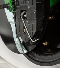
Set point row-unit downforce
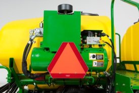
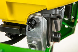
 Air compressor mounted on 1775NT outer hitch
On set point, the air compressor will be mounted on the outer hitch or frame assembly. Since the electric air compressor assembly is mounted on the outer hitch (as noted in the picture above) or frame, adjustments for row-unit downforce and related system pressures will be made electronically with the display.
When adjusting the amount of row-unit downforce using the display, the operator will select the amount of downforce (kg [lb]) to be applied across the planter. Depending on the soil conditions at hand, the operator might need to adjust the relative amount of row-unit downforce being applied during the planting operation. The integrated pneumatic downforce controls within the display will only allow for set-point operation and not automatic control as the planter is operating in different soil conditions. The pneumatic downforce system does not have the capability to automatically adjust downforce.
Pneumatic downforce provides convenient, simple adjustment of downforce for the whole planter from one location. The amount of downforce applied is infinitely adjustable from 6.8 to 181.4 kg (15 to 400 lb). Pneumatic downforce provides more consistent downforce throughout the range of row-unit travel than mechanical spring downforce systems.
Features include:
- 9.5-mm (3/8-in.) air delivery line instead of the 6.4-mm (1/4-in.) line used on model year 2010 and older planters.
- Air compressor assembly increased duty cycle. With this compressor, it provides a 47 percent increase in maximum air flow delivery compared to the prior air compressor.
- Pneumatic air bags with 9.5-mm (3/8-in.) air line inlets that have greater durability.
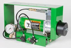 Pneumatic downforce compressor and gauge
An improved compressor is used to charge the pneumatic system. This compressor can be located on the planter frame or in the tractor cab if desired. A gauge at the compressor indicates the amount of downforce being applied.
Integrated pneumatic downforce system
The functional features of the integrated system are the same as the standard pneumatic system, explained above, with the addition of control through the display.
Heavy-duty adjustable downforce springs
 Heavy-duty adjustable downforce spring
Planter row-unit downforce is an important factor to ensure consistent and proper depth control. The heavy-duty adjustable downforce feature provides up to 181.4 kg (400 lb) of downforce. There are four settings available to allow the operator to choose the amount of downforce required for the condition: 0 kg (0 lb), 56.7 kg (125 lb), 113.4 kg (250 lb), and 181.4 kg (400 lb).
Row cleaner options to meet residue management needs
Crop yields have increased through the years along with the amount of residue left in the field after harvest. At the same time, tillage practices have changed, including different tillage operations which maintain large amounts of surface residue, and even no-till practices. Row cleaners are an essential tool in managing this increased amount of residue.
John Deere seeding group offers a variety of row cleaner options to meet the needs of a producer's operation. Compatibility varies by model, row spacing, and other planter equipment.
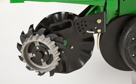
Screw-adjust, unit-mounted row cleaner
 Screw-adjust, unit-mounted row cleaner
The screw-adjust, unit-mounted row cleaner is mounted directly to the face plate of the row-unit, placing the ground engaging components just in front of the row-unit opener blades and depth gauge wheels. This close proximity allows the gauge wheels to control the depth of the row cleaner as well as the row-unit. This compact design also allows greater compatibility with fertilizer openers and other planter attachments.
SharkTooth® wheels are standard equipment on the unit-mounted row cleaner. The swept-tooth design of the wheel provides a clear path for the row-unit openers while resisting residue buildup on the wheel. The screw adjustment knob is accessible through the top of the parallel arms, providing convenient access for adjustments. The row cleaner can be adjusted in 1.6-mm (1/16-in.) increments, providing plenty of flexibility to meet the needs of changing conditions.
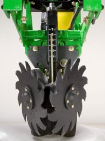
Floating row cleaner with unit-mounted coulter
 Floating row cleaner with unit-mounted coulter
The floating row cleaner allows a row cleaner to be used in conjunction with a unit-mounted coulter. This combination is often desired in heavy residue loads and reduced tillage planting conditions. The row cleaner provides a clear path for the row-unit, while the unit-mounted coulter helps penetrate tough soil conditions.
Accommodating the unit-mounted coulter means the residue wheels are farther forward from the row-unit face plate than in the case of the screw-adjust row cleaner. To maintain performance, this row cleaner has the capability to float above a defined minimum depth.
Standard depth-gauging bands on the wheels allow the row cleaner wheels to float independently of the row-unit openers, allowing both to perform in varying terrain. The unit may also be set in a fixed position by simply pinning through the bracket if desired. This row cleaner also features SharkTooth wheels as standard equipment.
The floating row cleaner and unit-mounted coulters are available on many planters as factory-installed equipment.
NOTE: Screw-adjust row cleaners are not compatible with MaxEmerge™ 5e row-units with long parallel arms.
NOTE: DB models have the option for either unit-mounted coulter, screw-adjust row cleaners, or pneumatic row cleaners (only compatible with MaxEmerge 5e or equipped ExactEmerge™ models). The DB60T is only available with a less row cleaner option.
SharkTooth is a trademark of Yetter Manufacturing, Inc.
Double eliminator - MaxEmerge™ 5 vacuum seed meters
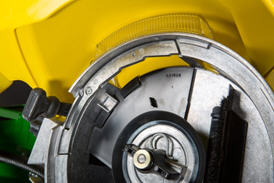 Double eliminator installed in MaxEmerge 5 meter
For difficult to singulate seeds, a flat seed disk and double eliminator is a viable alternative to traditional cell-type seed disks. By design, a flat seed disk requires higher levels of vacuum than a cell-type disk because there is no pocket or cell to hold the seed. The higher vacuum level will pull more than one seed to the holes in the seed disk. The double eliminator is set to cover a portion of the hole in the seed disk and is the mechanism to knock multiple seeds away as the disk rotates.
Double eliminators are required with flat-type seed disks only and should not be used with cell-type seed disks. The knockout wheel is also recommended in conjunction with the double eliminator and flat seed disk to ensure seed is ejected from the disk.
Double eliminator adjustment
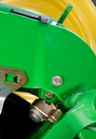
 MaxEmerge double eliminator adjustment knob
 Double eliminator numbered dial
The MaxEmerge 5 vacuum meter has an external, adjustable double eliminator. This double eliminator uses a knob with numbers to indicate where it should be set for different crops. This feature makes achieving a high level of singulation easier and more consistent.
The adjustment knob is capable of 21 unique positions. The dial is numbered zero through ten in increments of one, but the gearing allows for half increment adjustments as well.
Adjustment time for this double eliminator is estimated to be 10 seconds per row-unit, with repeatable results. This means that adjustment can be made three times faster than Pro-Series™ XP units, and eight times faster than MaxEmerge XP units.
Because flat seed disks require higher vacuum levels, planters with 12 row-units or more require two vacuum blower motors. In addition to vacuum blower requirements, 0-cm to 76.2-cm (0-in. to 30-in.) mechanical vacuum gauges would also be needed to monitor the elevated vacuum.
Seed variable-rate drive (VRD) with half- or three-width disconnect
 VRD shown on a 1775NT
The seed variable-rate drive provides the ultimate planting productivity by utilizing one, two or three hydraulic motors (varies by model) to turn the seeding drive shaft. Hydraulic control of the seeding drive allows for on-the-go seeding rate changes right from the display mounted inside the tractor cab.
Combine this seeding flexibility with the map-based planting option, and seeding rates adjust automatically based on a prescription map.
Single- or dual-motor systems for variable-rate drives are available for all John Deere planters except the 1785 Rigid Frame. Dual- or three-motor drive systems are commonly used on larger (12-row and more) planters and offer the capability of half-width or three-section drive disconnect.
The VRD is available as a factory-installed option for all applicable planter models. Single- or dual-motor systems are available as field-installed attachments for most planter models; however, a three-motor VRD field-installed attachment is not available.
The seed VRD requires the SeedStar™ monitor and a radar input signal. Either tractor or planter radar may be used. Planter radar is ordered separately.
VRD offers the following advantages over common, contact-tire drive systems:
- Almost instantaneous rate changes – there is no ramp up or ramp down of system as in some competitive systems
- Permits the operator to match seed population based on different soil types or irrigation practices
- John Deere design that provides added operator safety by eliminating any possible drive creep found in some competitive variable rate drive systems
Half-width drive disconnect
The half-width drive disconnect feature is excellent for the producer concerned with controlling seed costs. This feature helps the operator place seed in the desired area and limit the amount of costly overlapped planting.
The half-width drive disconnect allows the operator to turn off half of the planter at a time for planting end rows, point rows, etc. Variable-rate-equipped planters require two drive motors to utilize the half-width disconnect feature.
 Half-width drive disconnect within frame control
With a 1765, 1765NT, and 1775 12-Row Planter, a single switch box is required for planters that are ordered with variable rate drive and half-width disconnect.
For the 1775NT, 1775NT Central Commodity System (CCS™), and 1795 Front-Folding Planters, the half-width drive disconnect switch is contained within the frame control box, conveniently located in the tractor cab. The function easily shuts off the drive for the left or right half of the planter row-unit seed meters.
Three-width drive disconnect
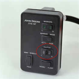
 Three-width drive disconnect control
Three-width drive disconnect is an option on 1725 12-Row Planters and is base equipment on the 1725 16Row30 Planter. This feature is activated by three individual console mounted switches (control box), conveniently located in the tractor cab. The function easily shuts off the planter row-unit seed meters by one-, two-, or three-drive segments independently.
Central Commodity System (CCS™) seed delivery system
 CCS
CCSCCS seed delivery adds productivity through increased seed capacity, bulk fill capability, and easy, thorough cleanout.
The two tanks have a combined capacity of 2466.7 L (70 bu) on 9.1-m (30-ft) planters and 3523.9 L (100 bu) on 12.2-m (40-ft) and larger planters. CCS tanks are manufactured using a rotomolded, polyethylene design to ensure maximum durability. The translucent tanks allow easily viewing the amount of seed in the tanks. The tanks are separated by 54.6 cm (21.5 in.) for enhanced rear visibility during transport and backing.
The following crops can be planted with CCS: corn, sweet corn, popcorn, cotton, sunflowers, sugar beets, soybeans, and sorghum (milo).
Filling the tanks is convenient due to a central filling location. The staircase and railing provide access to the filling platform between the tanks. If filling the tanks with an auger, minimum recommendations are a 15.2-cm (6-in.) diameter, 4.3-m (14-ft) auger. Each tank has an adjustable bin-level sensor to alert the operator when it is time to fill.
A standard fill light package is available on machines equipped with CCS. This feature includes two lights conveniently mounted on the railings of the machine. The lights are turned on and off with their own switch located at the bottom of the staircase.
If the seed-carrying vehicle requires hydraulic power to run the unloading system, the auxiliary hydraulic coupler option is available. These couplers are located at the bottom of the staircase and can be coupled under pressure. The system has a separate system filter that ensures the planter hydraulic system remains free of contaminates.
Seed delivery process
CCS is about reducing the time spent filling the planter with seed while maximizing the time spent planting. CCS for planters is a form of seed handling and delivery. The row-units perform the final task of seed metering and placement.
The CCS seed delivery process relies on a hydraulically driven fan to move seed from the CCS tanks to the row-unit hoppers. A flow control valve and gauge, located near the tank, allows for the proper tank pressure setting based on seed type. For normal operation, the CCS functions of fan and agitator control, as well as bin level sensing alerts, are controlled by status of the height switch. The CCS functions are enabled when the machine is lowered and disabled when the machine is raised. In addition, the CCS functions can be engaged for CCS hose cleanout using the switch on the back of the planter when oil flow is present. On models with software-based CCS control, CCS functions can be enabled or disabled through software interface in the cab as well as the switch on the back of the planter.
Air from the fan pressurizes the CCS tanks and delivers seed to the seed hoppers. Airflow enters the seed tanks through a nozzle in the manifold which pressurizes the tank. The air then picks up seed and moves it out the other end of the nozzle into seed delivery hoses. These hoses route the seed toward the hopper. A small amount of seed is traveling in the delivery hoses only when needed.
The hopper fills with seed until the delivery hose (discharge elbow) is covered. Once the opening is restricted, seed flow through the hose stops. Air flowing to the row-unit travels into the hopper and is the source of air for the vacuum system. This provides a much cleaner air source than previous meter designs. As the seed is picked up by the meter and planted, the seed pool shrinks until the end of the delivery hose is uncovered. At that time, the airflow and seed delivery resume and the seed pool in the hopper is replenished.
CCS tank scales for DB Planter models
The CCS tank scales for DB models are a stand-alone system from Digi-Star®. Load cells are installed at the factory and can be ordered for CCS or CCS with Refuge Plus.
There are three load cells, two at the rear of the CCS cradle and one at the front. They weigh both tanks as one; individual tank weights cannot be determined.
The load cells and display are made by Digi-Star. They are not on the controller aread network (CAN) bus system so they are not integrated into SeedStar™ software in any way. The monitor is sold separately through Digi-Star.
CCS seed cleanout
Seed cleanout could not be much easier with a CCS planter. When finished planting, any remaining seed can simply be removed via access doors at the bottom of the CCS tank.
Because seed is only traveling through the CCS delivery hoses when required by the meter, there is not much left to clean.
CCS seed delivery hoses are then purged with air from the CCS fan, and the excess seed is pushed to the individual meters. The vacuum meter door is opened and seed is removed with the supplied catch pan.
Small seed CCS components
 Manifold nozzle and nozzle with cover installed
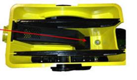 Straight seed inlet installed in mini-hopper
CCS seed delivery system increases planting productivity across the seven approved crops listed above. While highly effective delivering seed from the CCS tanks to the vacuum meters, small or light seeds (sorghum and small cotton) will require two additional components to aid in proper seed delivery.
Manifold nozzle covers (clips) should be installed to ensure seed is adequately picked up into the air stream for delivery to the row-unit. Mini-hopper discharge elbows should also be changed from the standard elbow (holes) to the small seed elbow (slotted openings) when planting sorghum (milo) and small cotton.
Digi-Star is a trademark of Digi-Star LLC.

We have a range of finance options to suit any customer. Contact your local Emmetts branch, or visit these sites for more information and a free quote.